The OP said the zener was bypassed with a big cap. Such an arrangement is in fact extremely quiet.Post 10 has the right idea. This is for a headphone amp so low noise should be a priority, in which case you should definitely scrap the noisy Zener. IMO
Update: i (kind of) followed Mooly's circuit and it works.
This is my current schematic.
Mooly's schematic shows a 2nd capacitor where the question marks are. Minor question and pretty sure the answer is yes, but in case i missed something, can i put 100uF cap there? I happen to have one lying around. I don't know, shorting that TIP122 and now using a sensitive MOSFET made me paranoid about transients.
This is my current schematic.
An externally hosted image should be here but it was not working when we last tested it.
Mooly's schematic shows a 2nd capacitor where the question marks are. Minor question and pretty sure the answer is yes, but in case i missed something, can i put 100uF cap there? I happen to have one lying around. I don't know, shorting that TIP122 and now using a sensitive MOSFET made me paranoid about transients.
Mooly's schematic shows a 2nd capacitor where the question marks are. Minor question and pretty sure the answer is yes, but in case i missed something, can i put 100uF cap there?
You don't normally put a capacitor in that position, since it will cause you to lose all the AC regulation that a regulator is supposed to provide! I'm not sure if it is a mistake in Mooly's diagram, or if he really means to regulate only DC and not AC (ripple).
Mooly?
You don't normally put a capacitor in that position, since it will cause you to lose all the AC regulation that a regulator is supposed to provide! I'm not sure if it is a mistake in Mooly's diagram, or if he really means to regulate only DC and not AC (ripple).
Mooly?
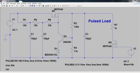
It wasn't a fully worked example tbh, a workable circuit yes, but not optimised.
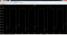
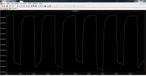
Here is the sim file (so you can alter and see the effect of changes). As it stands there is a pulsed load (severe test) and you can see the effect of making R6 either 15k or short and how the ripple alters. Its far less in amplitude with a cap fitted in that location. As always though, you need to balance all aspects of a design to best suit your needs.
Attachments
That's because the capacitor makes the circuit work as a capacitor multiplier, not a regulator! For a regulator you would normally have a capacitor in parallel with R3 (1 to 10uF say), which increases the feedback as far as AC is concerned, and tends to stabilise the regulator.Its far less in amplitude with a cap fitted in that location.
That's because the capacitor makes the circuit work as a capacitor multiplier, not a regulator! For a regulator you would normally have a capacitor in parallel with R3 (1 to 10uF say), which increases the feedback as far as AC is concerned, and tends to stabilise the regulator.
That's why I said you need to balance all the design aspects
")
Do you want max ripple rejection or best performance against transient load fluctuations. There is no one size fits all.
If the load is dynamic (and a headphone amp whether class a or class b) should in practice have minimal changes in supply current) then you need to look at what the min and max variation might be and over what time period.
I posted the sim file so that it can be tweaked by the user to suit the requirements.
- Status
- This old topic is closed. If you want to reopen this topic, contact a moderator using the "Report Post" button.
- Home
- Amplifiers
- Power Supplies
- Zener Follower - what did i do wrong?