Hi all, just a couple of quick questions for those more experienced than I...
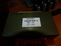
I am working on a power supply for an IRaud7s board and happened to come across this trans. from a Marantz SR2700. I estimated the VA at 330 which should be more than enough.
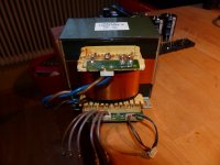
Question is why are there 5 taps on the secondary and how best should I go about creating a bipolar supply from it?
I am much more competent with tube power supplies, don't have much experience with solid state.
I only have the trans. so I cant check how it was done in the original receiver.
Any reccomendations?
I am working on a power supply for an IRaud7s board and happened to come across this trans. from a Marantz SR2700. I estimated the VA at 330 which should be more than enough.
Question is why are there 5 taps on the secondary and how best should I go about creating a bipolar supply from it?
I am much more competent with tube power supplies, don't have much experience with solid state.
I only have the trans. so I cant check how it was done in the original receiver.
Any reccomendations?
Attachments
It's a bit of guess work using the wire colours alone and a multimeter might not be accurate enough to ascertain what is going on using resistance.
It looks like you have two distinctly different sets of secondaries, one set are high power and the others are low power - simply from the gauge of the wire connected to them.
I would hazard a guess that the brown wire might be the centre tap.
I would power it up and measure the AC voltage between brown and all the other heavy gauge wires (the mauves).
If you use a domestic light bulb as a load you wont get any odd readings caused by the high input impedance of the meter.
I have already ohmed it out. The four wires on the right are two independent low voltage secondaries. The 5 wires on the left are the power section secondary.
My multimeter is not sensitive enough to measure accurately the DCR of these windings. I get around .8 to .9 ohms from end to end and .6 to .7 between the center ones.
I will hook it up to power tonight and check the voltages but I am curious as to the need of 5 taps on the secondary at all. does anyone have any experience with this sort of construction for a power transformer?
I have used power trans. for tube projects with 5 taps on the secondary; for instance 400-275-0-275-400 where a tube rectifier was used with a center tapped config. to yield either 400-0-400 or 275-0-275 for flexibility of circuit choices.
I just cant wrap my head around this sort of setup for a SS transformer where a bipolar supply is needed.
Another thought was to try to track down the schematic for the receiver in question but it seems easier to turn lead into gold...
I will have a look at the voltages shortly and report back.
Thanks for the replies guys
I will hook it up to power tonight and check the voltages but I am curious as to the need of 5 taps on the
secondary at all. does anyone have any experience with this sort of construction for a power transformer?
Hi,
MOSFET amplifiers are very poor at swinging to near the
rails at high output currents with a simple 3 wire supply.
Causes lower power and power disappation issues.
They need a 5 wire supply with two higher rails than
the output rails typically 6VAC higher than the main rails
to give about 10VDC more swing to the driver stage rails.
Note that the extra windings are piggy backed onto
the main windings, and don't have to be as high
gauge, so may well measure similar resistance,
rather than much lower, wound the same gauge.
rgds, sreten.
Last edited:
Sreten, Thanks for the reply. Does this mean that I can ignore the two outer windings and treat the secondary as a 3 tap center tapped secondary?
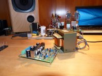
This will be for the IR reference design class-D IRAUD7s amp, I have estimated the trafo at around 330va which should be plenty.
This will be for the IR reference design class-D IRAUD7s amp, I have estimated the trafo at around 330va which should be plenty.
I just cant wrap my head around this sort of setup for a SS transformer where a bipolar supply is needed.
-Split supply for power amp
-Low voltage (12 V?) for line level stages and tuner
-5 V for logic circuits
This is exactly what you will find in many, many receivers.
They need a 5 wire supply with two higher rails than
the output rails typically 6VAC higher than the main rails
to give about 10VDC more swing to the driver stage rails.
Note that the extra windings are piggy backed onto
the main windings, and don't have to be as high
gauge, so may well measure similar resistance,
rather than much lower, wound the same gauge.
I missed this first time around.
If you have a 5 wire secondary and all 5 wires show continuity, then this is your explanation.
-Split supply for power amp
-Low voltage (12 V?) for line level stages and tuner
-5 V for logic circuits
This is exactly what you will find in many, many receivers.
What I meant was with the 5 wire sec.
I guess Sreten has it right.
- Status
- This old topic is closed. If you want to reopen this topic, contact a moderator using the "Report Post" button.
- Home
- Amplifiers
- Power Supplies
- Power transformer from Marantz SR2700?