I made SMPS for a car amplifier,
but there is un expectable spike on it
this is the waveform at IDLE

1A load (70v output)

heavy loads (<3A output)

this is data of my transformer

schematic
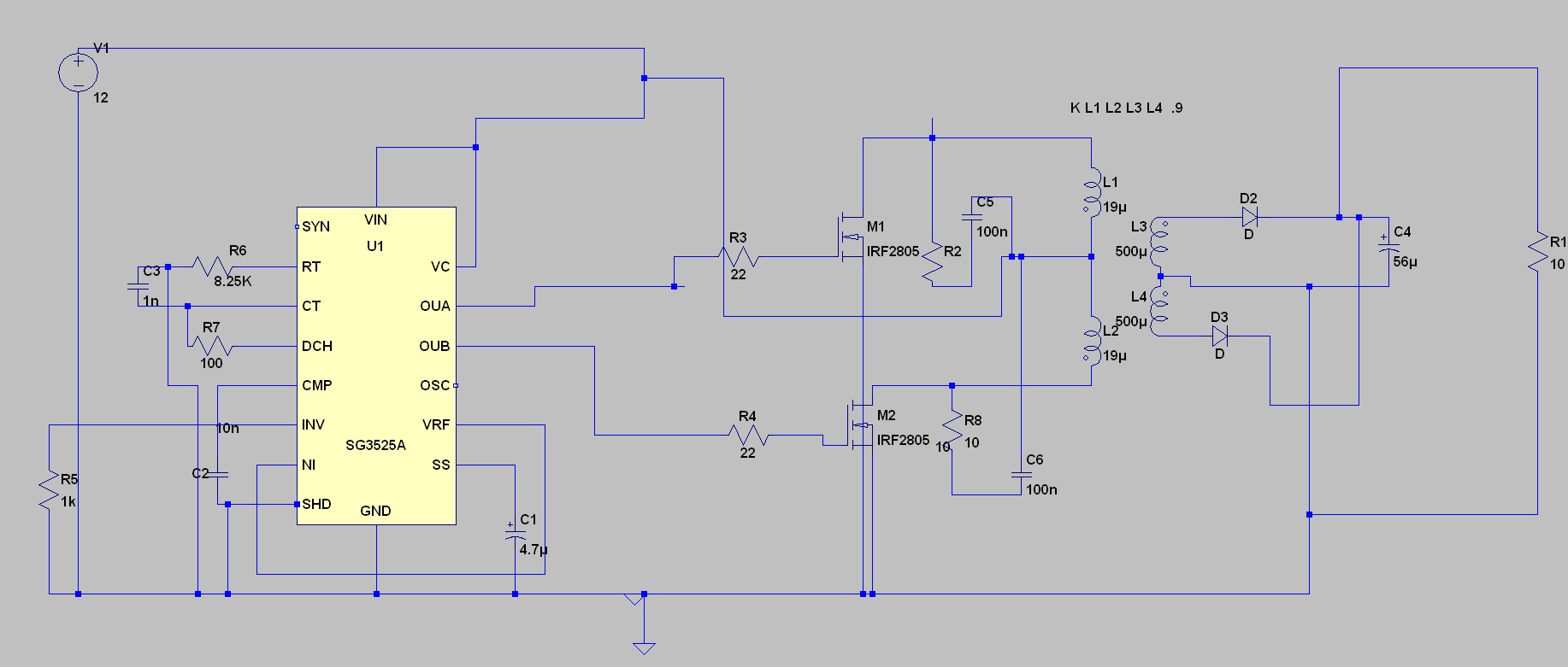
and testing on simulator

can u pleas tell me ,what is the reason of that matter.and what do I do to resolve this .
thank you.
but there is un expectable spike on it
this is the waveform at IDLE
1A load (70v output)
heavy loads (<3A output)
this is data of my transformer
schematic
and testing on simulator
can u pleas tell me ,what is the reason of that matter.and what do I do to resolve this .
thank you.

Good call infinia.
shouldn't it "CLC" instead of "LC" after diodes? 😕
I =C*dV/dt spikes
as load is increased average voltage drops ( normally from peak level) capacitor then shunts current due to exposed switch waveform rise time dV/dt .
Inductor feed will change output voltage which is reduced by duty cycle Vp*Ns/Np*D.
as load is increased average voltage drops ( normally from peak level) capacitor then shunts current due to exposed switch waveform rise time dV/dt .
Inductor feed will change output voltage which is reduced by duty cycle Vp*Ns/Np*D.
friends thanks for helping.
I tried your idea,insert a LC filter,
first 22uh no good result then 470uh same result
this is the circuit

I think
leakage inductance of transformer is the matter
Isolated Power Supply Is Suitable For Telecom/Datacom Applications - Application Note - Maxim
how to reduce leakage inductance from transformer
I tried your idea,insert a LC filter,
first 22uh no good result then 470uh same result
this is the circuit
I think
leakage inductance of transformer is the matter
Isolated Power Supply Is Suitable For Telecom/Datacom Applications - Application Note - Maxim
how to reduce leakage inductance from transformer
If you are buying these inductors look carefully at the date sheet. The current they give may be the saturation current. Your inductor should be able to handle about 5A with ripple current added in. So you may have to buy an 7 to 8A inductor to get 5A out of it. My best guess is you need a 760uH inductor
Also the 10uF capacitors on the output are way to small. My best guess on output capacitors is you need about .1 ohms MAX ESR. Look at the ESR ratings of electrolytic's around 2,200 to 3,300 uF at 100vdc
Also the 10uF capacitors on the output are way to small. My best guess on output capacitors is you need about .1 ohms MAX ESR. Look at the ESR ratings of electrolytic's around 2,200 to 3,300 uF at 100vdc
It looks very strange. I happened to make few them in the past and from my experience, you must have sort of free oscillation while it is in idle mode. On your picture I see that they are heavily suppressed. But any way, that spike is a product of transformer inductance. Faster you close your transistor bigger spike you gonna have. So, you can fix it by using another transformer or using suppressors. Or, make ur transistor closing slower but than you might have a short current, when one transistor is not fully closed but second one is already open. There is always a trade off.
And I would recommend split input from output by using TL431 + optocoupler. All people do it. Than with only one capacitor around TL431 you can play with CLOSE LOOP CONTROL speed. Which is good.
Something like this:
http://m.eet.com/media/1055481/C0475-Figure1.gif
Gee, I cant find the one that I used long time ago, but something similar is next. I do remember it was LRC snubber with DIODS and worked really well, the only thing is you have to adjust it to your push pull reality, cause it is hard to calculate, at least for me.
http://www.8085projects.info/wp-content/uploads/Passive lossless snubber circuit.jpg
-how to reduce leakage inductance from transformer? the only way is to redesign your transformer. Change material, or turns, or gap.
Last edited:
Leakage inductance can always be better! BTW it causes voltage spikes.
powerbob is correct > output caps ESR is used to calculate ripple at 2x fundamental switching frequency.
Don't reinvent the wheel look at some design guides. TI has some excellent resources. also some better 12V push pull schematics have been posted on the net
powerbob is correct > output caps ESR is used to calculate ripple at 2x fundamental switching frequency.
Don't reinvent the wheel look at some design guides. TI has some excellent resources. also some better 12V push pull schematics have been posted on the net
I found it
???????MOS????????_????_?????
Close to the end of the page, there is a picture of LCD lossless snubber. I have no idea how to calculate it, but I swear to Chuck Noriss, I saw it working very well indeed.
???????MOS????????_????_?????
Close to the end of the page, there is a picture of LCD lossless snubber. I have no idea how to calculate it, but I swear to Chuck Noriss, I saw it working very well indeed.
Attachments

I appreciate your help very much,
this is my whole project
300w classD car amplifier using IRS2092

PCB

this circuit is working perfectly,but it has only a trouble that i told before
this is my whole project
300w classD car amplifier using IRS2092
PCB
this circuit is working perfectly,but it has only a trouble that i told before
the transformer that I pick from another car amplifier working perfectly instead of my transformer


so what can I do for my transformer,
thank you
An externally hosted image should be here but it was not working when we last tested it.
so what can I do for my transformer,
thank you
It is either the way you wound the transformer or it is the core. Did you buy the core or salvage it.
the one the you took from real amp is good one, Toroidal transformer is actually best transformer people created. It has very good characteristics. If you spend some time reading about it you will find explanation for your problem. The ordinary transformer is not that good, but it is much easy to wire it. Which is good for production, allows you change output parameters really fast, makes possible to change transformer properties by introducing a little air gap in it.
So, Your original one is more for FLY BACK converters and stuff like that. Normally they have a little gap in the middle so you can run it in continuous or not continuous mode without going into deep saturation, but any way, these are not designed for 12 DC into +/- push pulls converters.
so, what can you do? Simple, buy a good toroidal transformer and this is it. Instead of fighting it, change it. Better spend some time on close loop stability control or some protections that sometime are necessity. And make sure you wire it properly. First goes secondary coil, second primary. In this way you gonna have minimal leakage inductance so spike when you close transistor.
Last edited:
It is either the way you wound the transformer or it is the core. Did you buy the core or salvage it.
I buy it from local electronic store.
the one the you took from real amp is good one, Toroidal transformer is actually best transformer people created. It has very good characteristics. If you spend some time reading about it you will find explanation for your problem. The ordinary transformer is not that good, but it is much easy to wire it. Which is good for production, allows you change output parameters really fast, makes possible to change transformer properties by introducing a little air gap in it.
So, Your original one is more for FLY BACK converters and stuff like that. Normally they have a little gap in the middle so you can run it in continuous or not continuous mode without going into deep saturation, but any way, these are not designed for 12 DC into +/- push pulls converters.
so, what can you do? Simple, buy a good toroidal transformer and this is it. Instead of fighting it, change it. Better spend some time on close loop stability control or some protections that sometime are necessity. And make sure you wire it properly. First goes secondary coil, second primary. In this way you gonna have minimal leakage inductance so spike when you close transistor.
sir,can you tell me good toroidial core for this
power out 350W-450W
frequency 50-70khz
1):10 Magnetics 0f 43615 TC Ferrite Toroid Cores | eBay
2):PC40 MnZn (OD=45mm ID=26mm T=15mm) black toroidal transformer ferrite core ,20PCS / lot-in Other Electronic Components from Electronic Components & Supplies on Aliexpress.com
or can you send me A link
How about this?
http://kgmagnetics.org/APNOTES-06/An-104.pdf
and
http://ww1.microchip.com/downloads/en/appnotes/01114a.pdf
I did it ages ago, but when you start read it you will see that it is quite simple. Avoid long and boring calculations, find simple one for beginner or dedicated software. In few words the product of multiplication (high * width) defines max power, another important parameter is Magnetic Material (or something similar) defines max operating frequency and loses. And last one is the Window area- how much you can put turns for particular wire. That is it.
Find the formula, do backward calculations and define Window Area, then power and based on this data you can choice particular toroidal transformer =)
It is hard to start but more you read, more you understand that is quite simple. Push Pull is simplest converter people ever invented.
Last edited:
Dinithm, It is nonsense that an E core or a EI core can not make a good inverter transformer. Toroids have good and bad aspects just as other core shapes have. The important thing is that you have the proper size and ferrite material. If you bought your core new, was it positivily identified or were you told it is "like" another core. Some cores do not have enough permeability to make good inverter transformers. Also some cores come pre gapped and you do not need a gap.
yes toroid is best esp for low voltage just like this. most car amps use it so.
you can use EI but need to use more interleaved windings for tighter coupling = lower leakage.
1st calculate pri turns based on cores Ae and volt*seconds use max Vin ~ 14 V at max flux density, then calculate Np/Ns using 60-75% duty cycle at nominal 12.7 Vdc.
copper losses > copper wire cross section area> use some constant. I use 500 Circular MILs per Ampere to calculate # of small wires on pri and sec.
the problem with size is to make sure you can get enough copper on it to keep cool.
my guess is around 60-75 mm OD with a decent Ae ( most any trusted ferrite used for SMPS is fine ) operating flux density is always about the same
Last edited:
- Status
- Not open for further replies.
- Home
- Amplifiers
- Power Supplies
- I need help ,SG3525 car amplifier smps