"That's All There Is - There Ai'nt No More -
Stop Stop Knocking At My Front Door -
I'm Thru - I'm Thru With You"
")
Thanks Mark for your insights and effort in bringing your skill to us, the DIY community.
I will certainly be watching out for any Gems you may have to share with us in the future.
Steve
I have a feeling that LTSPICE simulation might be able to answer the question in post #224, if circuit intuition cannot. You might as well get started building the simulation while you wait for other diyAudio members to post their circuit intuition.
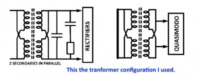
One possibility that you might try in simulation, is to devise some way to split the CRC snubber into two halves. Then put one half in chassis #1 and put the other half in chassis #2. Capacitors and resistors are small and inexpensive; it's probably not outrageously wasteful to use six of them per secondary, rather than three per secondary.
One possibility that you might try in simulation, is to devise some way to split the CRC snubber into two halves. Then put one half in chassis #1 and put the other half in chassis #2. Capacitors and resistors are small and inexpensive; it's probably not outrageously wasteful to use six of them per secondary, rather than three per secondary.
You've gotta laugh or cry when damn Windows program refuses to connect to the link - just a forerunner of the coming AI use for phone answering services, I guess.
I would put the reservoir caps (the charging caps) with the transformer, diodes and snubbers to reduce the current transients, noise, etc in the umbilical cables - I wouyld put secondary or power caps &/or regulators closer to active circuitry - need to be conscious of different grounding techniques as it's very easy to create problems here - I don't know if this is universal
I would put the reservoir caps (the charging caps) with the transformer, diodes and snubbers to reduce the current transients, noise, etc in the umbilical cables - I wouyld put secondary or power caps &/or regulators closer to active circuitry - need to be conscious of different grounding techniques as it's very easy to create problems here - I don't know if this is universal
First of all, since the probe is in parallel with the transformer secondary under test, you want the probe impedance to be much MUCH higher than the damping resistor Rs, else the probe itself will contribute to damping. For sensible real-world transformers, this means you want a probe impedance greater than 40K ohms. So: do NOT use 50 ohm RF probes and do NOT set the vertical amplifier Zin to 50 ohms.
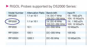
Secondly, I always prefer to use the setting which gives the highest bandwidth. For the Rigol DS2202 scope with the Rigol RP3300 probes, the highest bandwidth is achieved on the 10X setting: image below. So that's what I use, personally.
~
Secondly, I always prefer to use the setting which gives the highest bandwidth. For the Rigol DS2202 scope with the Rigol RP3300 probes, the highest bandwidth is achieved on the 10X setting: image below. So that's what I use, personally.
~
Attachments
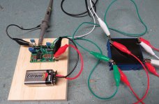
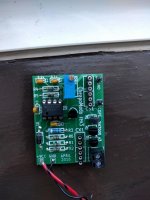
Here is my implementation of Mark's CheapoModo. I used his Rev. 3 Gerbers to have my own boards made.
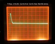
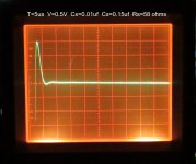
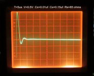
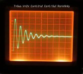
I believe I read most of the post here to learn how to best use this device. From my pictures I believe RS=58 ohms provides the best dampening. It looks like the picture using RS=50 ohms is a bit over dampened. Please advise.
I have 5 extra boards. I am offering these for the cost of shipping. Please respond via PM.
Attachments
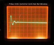
Dennis, congratulations! Looks like your board is working and your scope has a nice tight spot size. Be sure to trigger on the falling edge of the waveform on the "SCOPE" pin, this'll become pretty important when you start working with 400-800 VA toroidal transformers.
I absolutely LOVE this web page from Logwell; it helps me choose easy-to-buy, extremely common resistor values. In your case you want something somewhere between 50 and 58 ohms; if it were me, I'd consult Logwell and then choose 56 ohms, because it's in the E12 series and therefore, very easy and very inexpensive to buy.
I absolutely LOVE this web page from Logwell; it helps me choose easy-to-buy, extremely common resistor values. In your case you want something somewhere between 50 and 58 ohms; if it were me, I'd consult Logwell and then choose 56 ohms, because it's in the E12 series and therefore, very easy and very inexpensive to buy.
I've just completed building this board and think I having problems with it.
Is it correct to expect about 300mV pp, with VCC=12V with R-Core transformer connected?
At FETGATE I measured about 8V pp square wave which seems healthy.
I can't understand why the scope display of others are all above 5V. I hope someone can help.
Is it correct to expect about 300mV pp, with VCC=12V with R-Core transformer connected?
At FETGATE I measured about 8V pp square wave which seems healthy.
I can't understand why the scope display of others are all above 5V. I hope someone can help.
Hi Spikey - I haven't used the Cheapmodo, just Quasimodo. But I don't remember R-Cores as measuring much different than other transformers. A sketch or picture of your complete set-up as in post #232 would help. And I only ask this because I've done it myself.....but you don't have a 10X attenuation through the scope probe that's inadvertently not being considered, do you?
What's the Cheapomodo output without transformer connected?
Good luck -
Phil
What's the Cheapomodo output without transformer connected?
Good luck -
Phil
Remove RV1, remove Cx, remove Cs, remove transformer secondary. Look at FETGATE on scope, does it swing rail to rail?
Reinstall Cx. Look at FETGATE on scope, does it swing rail to rail?
Reinstall Cs and RV1. Look at FETGATE on scope, does it swing rail to rail? Look at node "SCOPE" on oscilloscope, is it centered at ground (0V)?
Insert a known-good, not-broken inductor (value unimportant, anything from 1uH to 1Henry) into terminal block and tighten the screws. Look at node "SCOPE" on oscilloscope. Is it centered at ground (0V)? Does it display the classical Quasimodo/Cheapomodo oscillatory ringing when you set the scope to trigger on the falling edge?
Remove the inductor and connect the secondary winding of the R-Core transformer into the terminal block, tighten down the screws. Look at node "SCOPE" on the oscilloscope. Is it centered at ground (0V)? Does it display the classical oscillatory ringing?
edit- could you wind 100 turns of insulated hookup wire around an iron nail and get an inductor that is acceptable for step 4? yes.
Last edited:
Thanks Mark and Phil for the suggestions and advice.
Just fyi, the middle FET seem hotter than the others, not scorching hot but hot enough to surprise me when I touched it accidentally. Not sure it is because I using a 12V lead acid battery rather than 9V or could be a faulty FET.
I do have a spare inductor so can use that and will go through the diagnostic steps, and hope to find the culprit.
I'll let you know how I get on tomorrow.
- Status
- This old topic is closed. If you want to reopen this topic, contact a moderator using the "Report Post" button.
- Home
- Amplifiers
- Power Supplies
- CheapoModo: quick and dirty transformer snubber bellringer jig