Hi,
I am looking at an existing power supply that I own and I am tracing the circuit as a learning exercise. It is for a condenser microphone that has a tube based circuit in the mic body.
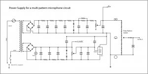
I have attached a schematic that I have drawn of the circuit.
I have been stopped by a misunderstanding on my part and am wondering if someone can help explain.
The top portion of the schematic shows the B+ supply and the topology seems familiar.
The 6.3vDC heater supply shown on the bottom half seems confusing to me. I have checked and double checked for accuracy of my interpretation of the actual layout and I think it is accurate. I can't understand why the electrolytic filter caps are oriented with the polarity as shown in the schematic. It seems like they are "backwards".
Additionally, I think the voltage regulator is functioning as a constant current source and I am not familiar enough with that implementation to determine if that has something to do with the orientation of the filter caps. I believe I have drawn the regulator as it is utilized but I was unable to view any labels that said in, out, adj so I have referred to a data sheet and hope I got it correct.
I'm hoping someone can recognize the idea behind this layout and explain how the polarity relates to this design.
Thank You.
I am looking at an existing power supply that I own and I am tracing the circuit as a learning exercise. It is for a condenser microphone that has a tube based circuit in the mic body.
I have attached a schematic that I have drawn of the circuit.
I have been stopped by a misunderstanding on my part and am wondering if someone can help explain.
The top portion of the schematic shows the B+ supply and the topology seems familiar.
The 6.3vDC heater supply shown on the bottom half seems confusing to me. I have checked and double checked for accuracy of my interpretation of the actual layout and I think it is accurate. I can't understand why the electrolytic filter caps are oriented with the polarity as shown in the schematic. It seems like they are "backwards".
Additionally, I think the voltage regulator is functioning as a constant current source and I am not familiar enough with that implementation to determine if that has something to do with the orientation of the filter caps. I believe I have drawn the regulator as it is utilized but I was unable to view any labels that said in, out, adj so I have referred to a data sheet and hope I got it correct.
I'm hoping someone can recognize the idea behind this layout and explain how the polarity relates to this design.
Thank You.
Attachments
The caps are correct. Positive end is at the top of all.
The regulator doesn't look to be in current mode, it looks to be floating one rail on another but doesn't look quite right as drawn. Given that the two windings produce two independent supplies, then there is no way that I can see that the input to the reg has any meaning as drawn. There is no return path for current flow from the top supply into the lower one that I can see.
The regulator doesn't look to be in current mode, it looks to be floating one rail on another but doesn't look quite right as drawn. Given that the two windings produce two independent supplies, then there is no way that I can see that the input to the reg has any meaning as drawn. There is no return path for current flow from the top supply into the lower one that I can see.
At first I was distracted by the idea that the series resistors were on the "negative" side.
I guess I just don't understand how the regulator works as it seems to me as if the connection that extends from the rectifier to the voltage regulators "OUT" should be directly connected to ground.
I think I am starting to see that the 6.3vDC output is on the positive side of the cap array and the load will return to ground even though I haven't illustrated that return.
I also see now that if I had simply drawn the regulator and the 2 poly film caps a little differently then the graphics wouldn't distract or fool me as much.
May I assume that one problem I am causing myself is that I am trying to understand the use of the regulator as a voltage regulator layout and this is a current source layout?
I had not studied using regulators as constant current sources yet. I guess I know what to do today.")
I will appreciate any further insights, comments, reality checks etc.
Thank you.
I guess I just don't understand how the regulator works as it seems to me as if the connection that extends from the rectifier to the voltage regulators "OUT" should be directly connected to ground.
I think I am starting to see that the 6.3vDC output is on the positive side of the cap array and the load will return to ground even though I haven't illustrated that return.
I also see now that if I had simply drawn the regulator and the 2 poly film caps a little differently then the graphics wouldn't distract or fool me as much.
May I assume that one problem I am causing myself is that I am trying to understand the use of the regulator as a voltage regulator layout and this is a current source layout?
I had not studied using regulators as constant current sources yet. I guess I know what to do today.
I will appreciate any further insights, comments, reality checks etc.
Thank you.
The caps are correct. Positive end is at the top of all.
The regulator doesn't look to be in current mode, it looks to be floating one rail on another but doesn't look quite right as drawn. Given that the two windings produce two independent supplies, then there is no way that I can see that the input to the reg has any meaning as drawn. There is no return path for current flow from the top supply into the lower one that I can see.
Thank You for your comment.
I don't want to presume that I understand your comment, but I wonder if I created the impression that I thought the two supplies are related.
The lower 6.3vDC supply is indeed separate from the B+ high voltage supply (apprx 120vDC).
The regulator is only intended to interact with the 6.3vDC supply.
I have been laying out a DIY from scratch PSU with a LM317 as a voltage regulator and that seems straight forward.
I have learned that some people use current source designs instead, and so that is why I have guessed that I may be looking at one and not realizing it... because I don't recognize it as the straight forward voltage regulator layout I was thinking about for my own DIY.
Thank You.
I now see there is something wrong with my schematic in the details around the regulator, the 6.3vDC tap, and the trim pot.
I'll have to scrutinize the layout and unlock the "puzzle".
Thank you for the time taken... I'll update this thread when I figure out what is going on with the actual circuit tracing.
Thank You.
I'll have to scrutinize the layout and unlock the "puzzle".
Thank you for the time taken... I'll update this thread when I figure out what is going on with the actual circuit tracing.
Thank You.
Hi,
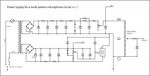
I think I got it right this time. I have attached a new schematic revision.
It is beginning to look, to me, like the regulator is acting as a voltage regulator.
On my DIY project I am planning to use a LM317 so that I can set the heater supply precisely at 6.3vDC once I have it powered from my local wall power and have the load attached.
I assume that the design I have been illustrating here is meant to do the same. I haven't made any adjustments because the mic works well right now.
I have a illustration of the parts layout that I drew up, but I am reluctant to post it publicly because it's not my design. It is just my drawing of a design of a PSU product that I own and use with a mic I purchased. Like I say, I am just hoping to learn something from the exercise of mapping it out as a schematic.
Please let me know if anything looks incorrect.
It is possible that I have the In and Adjust pins on the regulator backwards. I'm fairly sure about the Out pin as it is physically longer in the actual real life item.
Thank you for sending back to the drawing board!
Attachments
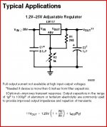
Firstly always have the data sheets handy for the devices you are using. You can get 99% free from here,
Datasheet catalog for integrated circuits, diodes, triacs, and other semiconductors, view
It still all looks a bit weird tbh. The lower rectifier produces ??? It will be the tranny Vac times 1.414. You have that rail marked as 6.3 volts, the regulator having no control over it.
The AC from the tranny should be rectified and smoothed... so far so good. The regulator then connects to that rail with the 6.3 volts coming from the output of the reg.
Like this, obviously with values to suit.
Attachments
Yes, It does look weird. That is why I am confused.
The data sheet you posted is the design I am using with my own DIY. It is also used in several other schematics and circuits I have studied.
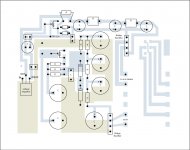
I have attached my drawing of the layout of the unit I have here and that I am trying to study. I stripped the part values etc. so as to just focus on the layout and routing rather than the specifics of the design.
I think this layout drawing is accurate and it is what I have based the schematic I have attached above was drawn from, so any mistake I have made with the layout drawing will show up in the schematic. I've checked several times to make sure I have the layout is correct. The change to the schematic I made this morning reflects a mistake I had made in translating the layout to a schematic.
As I mentioned, the regulator may be flip flopped and if that is the case it will be my labeling that needs correction rather than the line work as the line work is literal.
Thank again for taking a look. I welcome any further comments, observations, corrections, etc.
Thank You.
The data sheet you posted is the design I am using with my own DIY. It is also used in several other schematics and circuits I have studied.
I have attached my drawing of the layout of the unit I have here and that I am trying to study. I stripped the part values etc. so as to just focus on the layout and routing rather than the specifics of the design.
I think this layout drawing is accurate and it is what I have based the schematic I have attached above was drawn from, so any mistake I have made with the layout drawing will show up in the schematic. I've checked several times to make sure I have the layout is correct. The change to the schematic I made this morning reflects a mistake I had made in translating the layout to a schematic.
As I mentioned, the regulator may be flip flopped and if that is the case it will be my labeling that needs correction rather than the line work as the line work is literal.
Thank again for taking a look. I welcome any further comments, observations, corrections, etc.
Thank You.
Attachments
- Status
- This old topic is closed. If you want to reopen this topic, contact a moderator using the "Report Post" button.
- Home
- Amplifiers
- Power Supplies
- Question about Electrolytic Cap polarity