Psim and OrCAD Full Bridge Feedback & Output Voltage Problem
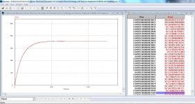
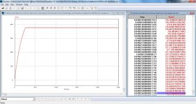
I've simulated my full bridge circuit via Psim but i cannot get a stable 370VDC at output. I calculated my feedback network according to Switching power supply design and Power supply cookbook. I've also used Basso's book. When i set the input voltage to lower value, output also goes down, and if i set the input to higher value, output also goes up, so feedback does not work. What's wrong with my circuit ? Could u pls help and give some advice ? I also do not know how to calculate the feedback network accuretly without having any network analyser. I've also tried to get bode plot but it will get something like 8 hours to get whole bode plot.
http://oi61.tinypic.com/b80lf9.jpg
Here is the result in OrCAD
Actually i do not know how to calculate feedback network accurately. I am really confused that which book is good for calculating. Since I've used marty brown's power supply cookbook, presmann's switching power supply design and basso's book. Pressmann's book does not tell anything about TL431 feedback with optocoupler. Marty Brown's book is pretty good but i am really confused to calculate some equations about feedback network. Basso's book is great but it needs some parameters such as needed gain and phase margin. So I've used Marty Brown's book for calculating but according this book, one resistor in compensation network in TL431 appears as 1054Mohm which is not realistic. Could you tell me which book you have been using for calculating feedback network and compensation ? I really need that. And I've also tried to simulate whole circuit via OrCAD but OrCAD always gives an error during the simulation. Here is the schematic and error.
INFO(ORPROBE-3183): Simulation running...
** Profile: "SCHEMATIC1-Full-Bridge" [ D:\Electrical & Electronics\Power Electronics\Simulation & Schematics\Orcad\full-bridge-pspi
Reading and checking circuit
ERROR(ORPSIM-16276): Can't find library
Circuit has errors ... run aborted
See output file for details
INFO(ORPROBE-3188): Simulation aborted
I am using UC3825 but it also says as follows:
WARNING(ORNET-1018): Connection to unmodeled pin U8 pin 'RT'
WARNING(ORNET-1018): Connection to unmodeled pin U8 pin 'CT'
I've simulated my full bridge circuit via Psim but i cannot get a stable 370VDC at output. I calculated my feedback network according to Switching power supply design and Power supply cookbook. I've also used Basso's book. When i set the input voltage to lower value, output also goes down, and if i set the input to higher value, output also goes up, so feedback does not work. What's wrong with my circuit ? Could u pls help and give some advice ? I also do not know how to calculate the feedback network accuretly without having any network analyser. I've also tried to get bode plot but it will get something like 8 hours to get whole bode plot.
An externally hosted image should be here but it was not working when we last tested it.
http://oi61.tinypic.com/b80lf9.jpg
Here is the result in OrCAD
Looking at the 653k resistor above your opto led. This dropping resistor limits current to 560 uA.
Are you certain the led lights up at all, to activate the phototransistor?
It is understandable if you wanted to use a high ohm value. It does not dissipate so many watts as heat.
However the led could need a milliamp or two, depending on its efficiency. This would require a lower value for the dropping resistor (about 150k). But then you'll need a higher watt rating.
By the way, what volt level did you set the TL431 to provide at its upper terminal? 2.52 V appears at the node between the 365k and 2.5k resistors.
Actually i do not know how to calculate feedback network accurately. I am really confused that which book is good for calculating. Since I've used marty brown's power supply cookbook, presmann's switching power supply design and basso's book. Pressmann's book does not tell anything about TL431 feedback with optocoupler. Marty Brown's book is pretty good but i am really confused to calculate some equations about feedback network. Basso's book is great but it needs some parameters such as needed gain and phase margin. So I've used Marty Brown's book for calculating but according this book, one resistor in compensation network in TL431 appears as 1054Mohm which is not realistic. Could you tell me which book you have been using for calculating feedback network and compensation ? I really need that. And I've also tried to simulate whole circuit via OrCAD but OrCAD always gives an error during the simulation. Here is the schematic and error.
INFO(ORPROBE-3183): Simulation running...
** Profile: "SCHEMATIC1-Full-Bridge" [ D:\Electrical & Electronics\Power Electronics\Simulation & Schematics\Orcad\full-bridge-pspi
Reading and checking circuit
ERROR(ORPSIM-16276): Can't find library
Circuit has errors ... run aborted
See output file for details
INFO(ORPROBE-3188): Simulation aborted
I am using UC3825 but it also says as follows:
WARNING(ORNET-1018): Connection to unmodeled pin U8 pin 'RT'
WARNING(ORNET-1018): Connection to unmodeled pin U8 pin 'CT'
Last edited:
Supplying good and legible graphics would certainly be a good advice: I have tried straining my eyes, even at the max magnification, but I have given up.What's wrong with my circuit ? Could u pls help and give some advice ?
Maybe younger people can help anyway?
Supplying good and legible graphics would certainly be a good advice: I have tried straining my eyes, even at the max magnification, but I have given up.
Maybe younger people can help anyway?
Yea sorry but i dont know how to show it correctly. I've just tried to save it on my desktop and it was easy to see the schematic. You can try that.
")
I have a video large monitor and I have OrCad, but this drawing is a difficult to read.
What size paper did you select?
I know, I selected large one. Just save image in your pc and open it there. I've just tested, it can be read. Actually i selected A0 paper in order not to sperate the circuit.
Even i put simple voltage divider feedback, output voltage never sets itself to 370V. I used 1k and 147k for voltage divider. When the input voltage is 30VDC, output becomes 357VDC, when the input voltage is 43.2VDC (three batteries in series), output becomes 376VDC. So, duty cycle cannot be set. It's always fixed i think. I cannot change it accurately. By the way, i didnt use anything for pin 3. So, error amplifier is now being used as open loop.
Attachments
- Status
- This old topic is closed. If you want to reopen this topic, contact a moderator using the "Report Post" button.