

No. Check what happens in your circuit when each pair of pairs of rectifier diodes conducts. You will find that you are trying to connect two different points to ground.
There are two ways to do what you want:
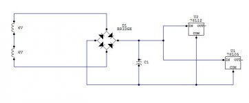
A. Use one bridge connected to the ends of the joined secondaries to provide an approximately 17V DC supply, which you can then regulate to 12V. Put a single rectifier diode from the CT to a reservoir cap to give you a 7V supply (which may be too small for 5V unless you use a low dropout regulator).
B. Separate the two secondaries and use one bridge for each, to form a centre-tapped DC supply.
There are two ways to do what you want:
A. Use one bridge connected to the ends of the joined secondaries to provide an approximately 17V DC supply, which you can then regulate to 12V. Put a single rectifier diode from the CT to a reservoir cap to give you a 7V supply (which may be too small for 5V unless you use a low dropout regulator).
B. Separate the two secondaries and use one bridge for each, to form a centre-tapped DC supply.
Thanks for your input folks.
The reason I'm splitting it is because the 12V rail will draw more current than the 5V and also i think the voltage delta from 15V to 5v is a lot to drop on a regulator.
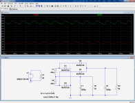
I had a quick play around in LTspice and came up with this (it appears to work):

The reason I'm splitting it is because the 12V rail will draw more current than the 5V and also i think the voltage delta from 15V to 5v is a lot to drop on a regulator.
I had a quick play around in LTspice and came up with this (it appears to work):

It takes four more diodes than the solution I proposed, and why not if you're intent on brewing you own solution, but there is something more worrying: since you're on LTspice, I'd check the current through D3 and D7 (maybe some other diodes too, but these are the most obvious)I had a quick play around in LTspice and came up with this (it appears to work):
The second circuit is not quite as bad as the first one; at least it will work. You have 8 diodes. Only 2 of them do anything useful. Hint: you have made two half-wave rectified supplies.
Why not try my suggestion, or Elvee's suggestion? Either will work. His is essentially the same as my suggestion A, but he omits an (almost) unnecessary diode which I included.
Why not try my suggestion, or Elvee's suggestion? Either will work. His is essentially the same as my suggestion A, but he omits an (almost) unnecessary diode which I included.
Apologies in advance, I should have mentioned that I have only bridge rectifiers hence the reason I keep putting so many diodes in the circuit, I don't normally use ltspice and could not find the rectifier part in the library. As a quick fix for tonight I will cobble it together as I have but for a more permanent solution I will use the schematics that you have posted after I purchase some diodes.
Thanks
Dom
Thanks
Dom
The circuit I posted uses a bridge rectifierApologies in advance, I should have mentioned that I have only bridge rectifiers
And as an added bonus, it will keep everything nice and warmlm7805 is rated for up to 30 volts input. It doesn't matter if the 12V reg will draw more than the 5V, it will still be 12 and 5 on the reg outputs.
Think about what happens whendomyboy said:I can see how DF96 solution A would work but the 6v output on elvee schematic I don't understand how the 6V isn't more like an ac wave?
a) the diodes are conducting (at the AC cycle peaks)
b) the diodes are not conducting (the rest of the AC cycle)
And as an added bonus, it will keep everything nice and warm
If the heat is a concern, you can add a resistor and capacitor in front of the 5V reg to drop some volts and this will also isolate it from the 12V reg if the current difference bugs you that much. Sometimes more complicated doesn't mean better, it just means more complicated.
Does it matter? A circuit doesn't need your understanding or lack thereof to work -or not-.but the 6v output on elvee schematic I don't understand how the 6V isn't more like an ac wave?
If the result suits you, simply use it. You can always attempt to grasp an understanding of how things work at the lower layers, but it is completely optional. It's somewhat like quantum mechanics: you only need the good recipe to get the result right, the rest boils down to operational details
- Status
- This old topic is closed. If you want to reopen this topic, contact a moderator using the "Report Post" button.
- Home
- Amplifiers
- Power Supplies
- AUX PSU Check