hi guys,
how can i calculate the turns that i have to make to the core acording to AL?
i am building a psu that uses etd44 core....
but i have an ungaped er54 core and i want to use it..
the mosfet can handle the extra power....
with the etd 44 it needs 24 turns at the primary...
how many turns should i make at er 54 core in order to get the best out of it?
here are the datasheets...
http://www.epcos.com/inf/80/db/fer_07/etd_44_22_15.pdf
http://www.epcos.com/inf/80/db/fer_13/er_54_18_18.pdf
and something else...
how can i calculate the thiknes of the enameled coper i have to use?
don't change the thickness. The thickness/thinness is chosen to suit the very higher frequencies..................
how can i calculate the thiknes of the enameled coper i have to use?
For high current capability you increase the number of parallel windings.
Look at the standard SMPS in a PC. It could have 6 paralleled windings to give the current capability required from the thin wire needed at the high frequencies.
andrew thanks for your reply but the problem is that i don't know the thiknes...
if you look at the site with the schematic you ill see that it doesnt mension anything aboyt the coper thiknes...
it says only about the turns....
i dont know the thiknees of the copper he is using....
if you look at the site with the schematic you ill see that it doesnt mension anything aboyt the coper thiknes...
it says only about the turns....
i dont know the thiknees of the copper he is using....
Hi!
He is firing with 50kHz, so he is probably using around 0.5mm - 0.6mm wire.
Put as many in parallel as you can to the core, so that the core will be wound full of wire when ready.
Primary about 20turns to that core.
You have noted, his PCB has about zero clearance between primary and secondary, have you? So do not let your children get close to that PSU...
Can you wound that core so, that you have the safety clearances between the primary winding and the secondary winding in it?
How much clearance do you need in your offline transformer between the primary and the secondary? (and PCB...)
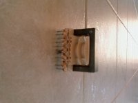
Re image post #8 don't use that split bobbin, you want to wind the secondary over the primary to get close coupling at high switching frequencies > 10KHz
usually best results to interleave multiple primaries too. Without adequate close coupling expect much more leakage inductance resulting in greater snubber losses and even MOSFET failure.
bobbin>pri>sec>pri ( > 2to 3 layers of insulating tape )
use at least several strands in parallel to fill the whole width of the bobbin leaving 4mm margins at both ends. IE safety creepage is 8mmm total at offline voltages.
what AWG magnet wire do you have available?
For baseline I use 500 circular mils per Ampere copper loss calculations 40deg rise no air
see wire chart for dimensions and cross sectional area http://www.ihiconnectors.com/AWG%20wire%20sizes.htm
Last edited:
"with the etd 44 it needs 24 turns at the primary..."
source? use new cores center leg area for reduced turns.
using the same core material adjust the turns downward by the core legs area %, holding the secondary to primary ratio as a constant.
ideally you set the operating flux density B to equal the copper losses.
but practically copper losses are much more, cuz all the insulation, margins, and wires skin effect>
Last edited:
hi guys,
how can i calculate the turns that i have to make to the core acording to AL?
i am building a psu that uses etd44 core....
but i have an ungaped er54 core and i want to use it..
the mosfet can handle the extra power....
with the etd 44 it needs 24 turns at the primary...
how many turns should i make at er 54 core in order to get the best out of it?
here are the datasheets...
http://www.epcos.com/inf/80/db/fer_07/etd_44_22_15.pdf
http://www.epcos.com/inf/80/db/fer_13/er_54_18_18.pdf
and something else...
how can i calculate the thiknes of the enameled coper i have to use?
I do remember downloading a little software from EPCOS web page which allows you to calculate anything relate to their ferrit cores (turns, loses, power inductance and so on) , but it was more then 6 years ago. But I do remember.
with the etd 44 it needs 24 turns at the primary...
how many turns should i make at er 54 core in order to get the best out of it?
ET54 core has 53% more area on the center leg (Ae). Running it at the same flux density as the ETD 44 you must reduce primary turns by 50% or 1/2 . Thus keeping the turns ratio constant gives 12T turns on the primary and 5T on the secondary.
But this isn't that important cuz you will never utilize the most power from the huge core , unless you change the whole design.
again the split bobbin is not appropriate for a straight half bridge converter anyway, so you might file it off or just buy the right core set.
what's the plan for the PCB design?
ok i will not use this robin....
i have ER54 core not ETD54....
instead of irfp450 i will use irfp460 in order to handle the extra power..
what else i have to change?
can i use 4 picies of 0.7 mm copper for the primary cause i have a lot or it needs thiner wire and more picies in parallel?
here is the pcb http://www.classdaudio.tk/doc/Offline SMPS/Smps (Mos-Fet) vr.5 PCB.pdf.pdf
19 AWG should be OK, 1st draw up the proposed windings design using the new bobbin. , use the bobbin full width, minus safety margin. again 500 MILS / Ampere to decide how many parallel wings on the primary and the secondary. Figure out the average power you will really need in your application any extra is OK but don't put the design at risk >more power can be had by using fan cooling.
turns /layer ( max ) = (bobbin width - 8mm) / wire dia
probably can wind 4 secondary winding on one layer (some in parallel) for better regulation
turns /layer ( max ) = (bobbin width - 8mm) / wire dia
probably can wind 4 secondary winding on one layer (some in parallel) for better regulation
Last edited:
He is talking about circular mils.
500cmils is around 0.25mm2, which is about a 0.6mm dia wire.
Then 1 of these wires / 1 Ampere in the winding...
You want 2 amperes, you put two 0.6mm wires parallel, and so on...
But do not calculate the transformer current output this way.
You only prevent the heating of the wires by this .
500cmils is around 0.25mm2, which is about a 0.6mm dia wire.
Then 1 of these wires / 1 Ampere in the winding...
You want 2 amperes, you put two 0.6mm wires parallel, and so on...
But do not calculate the transformer current output this way.
You only prevent the heating of the wires by this .
40%
it's OK just make sure secondary covers the same "footprint"
huge core for a lil half bridge how is that going to fit on the PCB?
I don't think you would ever fully utilize that huge core unless using a full bridge say at 1000W.
thinking out loud> why don't you design it for a smaller core and just build it on that oversize beast, you know for testing purposes.
- Status
- This old topic is closed. If you want to reopen this topic, contact a moderator using the "Report Post" button.
- Home
- Amplifiers
- Power Supplies
- ferite core turns