Hi,
I have been looking at various designs for tube heater DC power supplies and now I am trying to learn about how to use a LM317 type voltage regulator.
I've been looking at the basic application schematic and reading explanations about how the components interact.
There's one thing I can't quite figure out. How do you figure out how much current capability the transformer needs to supply the system?
I want to have power for one heater element with a current rating of 0.150A and I see LM317s with outputs of 0.500A as well as 1.5A. I'm trying to figure out how to combine the current needs of the tube's heater element with the current used by the LM317 itself.
I guess what I mean is that I am assuming that a 317 that provide 1.5A needs more than 1.5A from the transformer.
I've been trying to read up on this but I keep finding myself reading about the applications instead of this basic question.
Can someone point me in the right direction to learn what I need to figure out?
Thank You.
Dumb questions don't exist. We all had to start somewhere.
The 0.5A and 1.5A figures are the maximum current ratings of the LM317, depending on the package it is in. The actual load presented to the LM317 by e.g. heaters can be much lower than this. The transformers' power rating should be chosen based on that actual load plus some other factors.
The LM317 itself almost doesn't use any current at all. There's some current going to the adjustment pin of about 50 uA, which is negligible. The current going THROUGH the LM317 is the load presented by the heater + the resistors network used to set the output voltage. Assuming you want to get 12,6 volts, based on the 150mA preference, the transformer could be a 12V type. So if for example 5mA flows through the resistor network and 150mA through the heaters (155mA total), a minimum rating of 1,86VA could be used, but because of the strain of the charging pulses and heat buildup, a higher VA rating is to be used.
Last edited:
At the risk of seeming like I went from dumb to smarter... I guess I thought it was more complicated than that. ")
I thought that a regulator like that had to "waste" some energy, so to speak, to provide a constant voltage level.
If I work up a design for a single heater element rated for 0.15A draw at 6.3vDc will a transformer with a 12vAC secondary and a 0.3A rating work out ok?
Thank You.
I thought that a regulator like that had to "waste" some energy, so to speak, to provide a constant voltage level.
If I work up a design for a single heater element rated for 0.15A draw at 6.3vDc will a transformer with a 12vAC secondary and a 0.3A rating work out ok?
Thank You.
Your assumptions are wrong. I recommend you study Ohm's law, here:https://www.google.com/#q=ohm%27s+law , and Thevenin and Norton Equivalent Circuit Analysis, here:https://www.google.com/#q=thevenin+and+norton. Both are essential to answering your question. After you get answers to your rudimentary questions, more enlightened questions will surely follow, and then we will be in a better position to help you.
Mike
Mike
The LM317 does waste energy. The difference in in- and ouput voltage is converted into heat and dissipated that way. Also, there is a minimum voltage difference for it to start regulating. Things to take into account when selecting a transformers' voltage rating.
A 12VAC transformer is a bit overkill. It will provide roughly 17V Peaks after rectification. Minus the diode's voltage drop and allowed ripple voltage, you're left with around 14V. At 6.3V output, the LM317 has dissipate around 8V@150mA which makes 1,2W. A transformer with an output voltage closer to the output, while accounting for variations in mains and components will lower this dissipation figure so less heat will be produced.
A 12VAC transformer is a bit overkill. It will provide roughly 17V Peaks after rectification. Minus the diode's voltage drop and allowed ripple voltage, you're left with around 14V. At 6.3V output, the LM317 has dissipate around 8V@150mA which makes 1,2W. A transformer with an output voltage closer to the output, while accounting for variations in mains and components will lower this dissipation figure so less heat will be produced.
Dumb questions don't exist. We all had to start somewhere.
The 0.5A and 1.5A figures are the maximum current ratings of the LM317, depending on the package it is in. The actual load presented to the LM317 by e.g. heaters can be much lower than this. The transformers' power rating should be chosen based on that actual load plus some other factors.
The LM317 itself almost doesn't use any current at all. There's some current going to the adjustment pin of about 50 uA, which is negligible. The current going THROUGH the LM317 is the load presented by the heater + the resistors network used to set the output voltage. Assuming you want to get 12,6 volts, based on the 150mA preference, the transformer could be a 12V type. So if for example 5mA flows through the resistor network and 150mA through the heaters (155mA total), a minimum rating of 1,86VA could be used, but because of the strain of the charging pulses and heat buildup, a higher VA rating is to be used.
Thanks very much for elaborating!
I was just off looking at the resistor network and figuring out what you have explained.
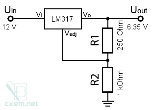
I added the 0.15A heater draw to the resistor network as shown in this example:
0.15A + (6.3vDC/1250ohm = 0.005A) = 0.155A
VA = 0.155A x 12vAC transformer secondary = 0.186VA
Step by step... I'll keep trying to learn.
Thank You!
I thought that a regulator like that had to "waste" some energy, so to speak, to provide a constant voltage level.
It does waste energy, but as funk1980 says, the current through the regulator is near enough the same as the output current. There will be a voltage across it and current through it, so it will dissipate Watts (might need a heatsink) and waste energy as you say.
Your 12V transformer should be fine (you might be OK with 9V) and I would add a small heatsink to the regulator: 12VAC peak = 17V - 6.3V = 10.7V (across the regulator) x 0.15A = 1.6 Watts
HTH,
Brian
The LM317 does waste energy. The difference in in- and ouput voltage is converted into heat and dissipated that way. Also, there is a minimum voltage difference for it to start regulating. Things to take into account when selecting a transformers' voltage rating.
A 12VAC transformer is a bit overkill. It will provide roughly 17V Peaks after rectification. Minus the diode's voltage drop and allowed ripple voltage, you're left with around 14V. At 6.3V output, the LM317 has dissipate around 8V@150mA which makes 1,2W. A transformer with an output voltage closer to the output, while accounting for variations in mains and components will lower this dissipation figure so less heat will be produced.
I was looking at 78XX series designs and got hung up on the idea that you need something like 10.5vAC minimum to get a 6.3vDC output. I will rethink the idea of using a 12vAC secondary with the LM317 and work towards better efficiency.
This is the first time I have thought about a DC heater supply. I have some basic experience with 6.3vAC heater supplies and so I'm trying to figure out what the various choices are with DC designs.
Thank you very much for your time and thoughtful help.
Hi,
FWIW regulation is overkill comparing AC and DC heater supplies.
If you can arrange a suitable rectified and smoothed DC supply
its usually well good enough for the job, compared to AC,
noting bifilar heater windings cancel the AC field.
rgds, sreten.
I have to disagree. The biggest advantage IMO is the heater supply being immune to variations in input voltage and electrolytics degradation. Another plus, amongst others, is the wide range of transformers that can be used.
And lets not forget the option for a CSS (with or without a LM317), providing excellent operation stability during the tube's lifetime.
Last edited:
I added the 0.15A heater draw to the resistor network as shown in this example:
0.15A + (6.3vDC/1250ohm = 0.005A) = 0.155A
VA = 0.155A x 12vAC transformer secondary = 0.186VA
No. The VA rating of the secondary comes by multiplying its voltage and the rms current that flows through it.
You require 155mA DC load. But you will have a reservoir cap after some rectification that will store charge after current pulses from the transformer will be injected into it. These pulses will have an rms value greater than 0.155A, since the capacitor implies that power factor is not 1.
To cut the story short, I would expect that this rms value will be typically be 1.5-2.5 times the DC load current. Which means that your VA rating shall be around 3-5VA.
And, double-check your math. 0.155 X 12 = 1.86.
Thank You for explaining about the power factor and the pointing out the need to account for the capacitor charge cycles.
Thanks for the correction with the math! I made a typo error with that.
The transformer AC current rating must be greater than 2times the continuous DC current consumption when using a capacitor input filter to generate the DC voltage/current.
I recommend approximately 4times to allow the winding to run at 50% of the maximum rating.
eg a 6.3V feeding a 50ohm (hot) filament will demand 0.126A when hot.
The AC rating of that winding must be >0.252A and preferably ~500mAac for the 50ohm filament.
If the hot filament has a 10ohm resistance then the arithmetic becomes V/R = Idc
Iac = 4 * Idc.
Have you considered using a CCS supply for the filament rather than a regulated voltage?
A 317 wired as a CCS works very well.
Hi Andrew,
Thanks for the info about transformer sizing.
I was aware that I could consider a constant current design but I don't know much about them and I haven't learned enough about them yet.
At this point I'd like to start with a LM317 as voltage regulator implementation to get some first hand experience with that.
Thank You.
- Status
- This old topic is closed. If you want to reopen this topic, contact a moderator using the "Report Post" button.
- Home
- Amplifiers
- Power Supplies
- dumb question about LM317 series.