Been looking at ways to improve the old LM317 and I got the idea to use a TL431 as a reference.
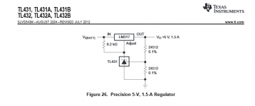
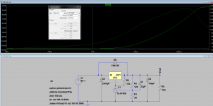
Looking at the TI TL431 datasheet, at page 30 you find the implementation shown in attachment 1.
TL431 is used as a reference at the LM317 ADJ leg, with a 8K2 resistor from input to ADJ leg. TL431 cathode current varies with input voltage.
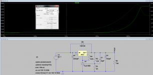
I changed the resistor to 820R, with the TL431 set up for 17.5V OUT and that gives a current through the TL431 of 10.8mA with a 25V input voltage
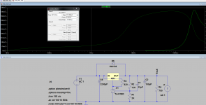
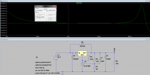
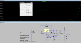
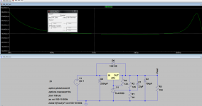
Attachment 2, 3 and 4 shows the rejection, impedance and noise of this implementation.
So far it seems to work very well, rejection is standard for LM317, the output impedance however, looks way to good to be true, the noise looks fairly standard for a LM317 regulator.
However, what if we move the 820R resistor from the Input to the Output? Well, that I did, and I now reduced it to 120R which gives the same 10.8mA through the TL431. This current would now be fixed at 10.8mA(as fixed as it can be with the 1.25V reference in LM317).
Attachment 5, 6 and 7 shows rejection, impedance and noise of this implementation.
The rejection improvements are substantial, looks like the Lm317 and TL431 rejection is added? Output impedance is one tenth of the datasheet implementation? Noise however, doesn't change much.
Can the improvements in rejection and output impedance really be true or is this some kind of LTSpice fluke?
Any other possible issues with this implementation, like stability issues?
Looking at the TI TL431 datasheet, at page 30 you find the implementation shown in attachment 1.
TL431 is used as a reference at the LM317 ADJ leg, with a 8K2 resistor from input to ADJ leg. TL431 cathode current varies with input voltage.
I changed the resistor to 820R, with the TL431 set up for 17.5V OUT and that gives a current through the TL431 of 10.8mA with a 25V input voltage
Attachment 2, 3 and 4 shows the rejection, impedance and noise of this implementation.
So far it seems to work very well, rejection is standard for LM317, the output impedance however, looks way to good to be true, the noise looks fairly standard for a LM317 regulator.
However, what if we move the 820R resistor from the Input to the Output? Well, that I did, and I now reduced it to 120R which gives the same 10.8mA through the TL431. This current would now be fixed at 10.8mA(as fixed as it can be with the 1.25V reference in LM317).
Attachment 5, 6 and 7 shows rejection, impedance and noise of this implementation.
The rejection improvements are substantial, looks like the Lm317 and TL431 rejection is added? Output impedance is one tenth of the datasheet implementation? Noise however, doesn't change much.
Can the improvements in rejection and output impedance really be true or is this some kind of LTSpice fluke?
Any other possible issues with this implementation, like stability issues?
Attachments
-
 Datasheet.png14.9 KB · Views: 5,294
 -
 LM317-TL431-Rejection-Datasheet.png61.5 KB · Views: 4,404
 -
 LM317-TL431-Impedance-Datasheet.png59.7 KB · Views: 4,163
 -
 LM317-TL431-Noise-Datasheet.png54.3 KB · Views: 3,985
 -
 LM317-TL431-Rejection-Alternative.png58.5 KB · Views: 3,912
 -
 LM317-TL431-Impedance-Alternative.png57.1 KB · Views: 1,136
 -
 LM317-TL431-Noise-Alternative.png51.2 KB · Views: 1,546
Last edited:
Where do you have the DC voltage?
Look at the schematic on attachment 2, to the left of V1 is the number 25......
Do you get any DC voltage out also?
Off course I do, 17.5 Vout just as I wanted.
Been using LTSpice for a few years now and I think I know how to use it.
")
If I simulate the LM317 in a typical datasheet implementation(R1=120R, R2=1K5//C=22uF, 17.5 Vout), it performs more or less as you would expect from the datasheet with regards to rejection, impedance and noise so the way I simulate it should be just fine.
So what are you trying to say?
Does your TL431 model incorporate it's reactive components? The TI model was really only thermally sensitive.
When you bode plot the LM317 it's important to reference the analyzer inputs to output rather than ground.
For your first comment :
I am using the model from here : Realistic SPICE model for TL431: stability, noise, impedance and performance simulation of TL431 shunt regulator | Audio PerfectionAudio Perfection
The "Eugene" model, it is the most accurate model available, matches the datasheet very well. Models, DC, AC, Noise, Transient and Output impedance.
As for your second comment, what?
As for your second comment, what?
The LM317 voltage reference is compared to the output not ground. See this application note from omicron-lab:
http://www.omicron-lab.com/fileadmi...notes/App_Note_Noninvasive_Stability_V1_2.pdf
I use Christophe Basso's TL431 model -- he's written an exhaustive (!) paper on the topic:
http://cbasso.pagesperso-orange.fr/Downloads/Papers/The TL431 in loop control.pdf
The LM317 voltage reference is compared to the output not ground.
And what does this mean for my simulation? If I were to make a real world bode plot, sure it has to be referenced to the output and not ground but for a simulation I do not ssee the issue.
Interesting files you linked to.
How good is his model and where can I get it?
Last edited:
Further simulation shows that it is C1 that gives me these exaggerated results. If you instead of having it between TL431 Vref and LM317 Out, you place C1 between TL431 Vref and TL431 Cathode, you get the normal LM317 rejection, impedance and noise. Though low frequency rejection is improved a lot as one would expect.
Interesting, the question now is, why?, and what does it mean.
Interesting, the question now is, why?, and what does it mean.
Last edited:
Inclusion of the TL431 in the feedback path increases the open loop gain by the TL431's 55dB small signal gain. Like any amplifier output error is therefore reduced by the additional excess loop gain. You can assess stability by checking the phase margin same as any other composite amplifier. The basic stability criteria is the output device needs to be faster than the control loop (see Linear's AN-47; if memory serves you want appendix C). So, given the 317 has about a 10kHz regulation bandwidth and the TL431 a 100kHz regulation bandwidth, there'll likely be tears unless compensation is applied.
Shunting the TL431 with a decent size cap like C1 effectively removes it from the feedback loop. Hence the reversion to regular 317 performance.
Essentially what you're doing is implementing a super regulator. There's an abundant literature on those which you can consult.
Shunting the TL431 with a decent size cap like C1 effectively removes it from the feedback loop. Hence the reversion to regular 317 performance.
Essentially what you're doing is implementing a super regulator. There's an abundant literature on those which you can consult.
Great answer, just what I was looking for.
Compensation something which has an output device that is only 1/10 the speed of the control loop would be a real pita. I think I will just go ahead and use the TL431 as a standard low impedance reference for the LM317 and keep it out of the feedback loop. It still gives me great low frequency ripple rejection and that was what I was after to begin with.
Compensation something which has an output device that is only 1/10 the speed of the control loop would be a real pita. I think I will just go ahead and use the TL431 as a standard low impedance reference for the LM317 and keep it out of the feedback loop. It still gives me great low frequency ripple rejection and that was what I was after to begin with.
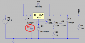
You could increase line/load rejection by splitting the TL431's cathode bias resistor into two series pieces, then bypassing the midpoint to ground with a BFC. The "+3dB benefit point" is approx BFC>10uF for Fig.1, BFC>68uF for Fig.5. Cost=low, benefit=high, decision=easy.
By the way, as Fred Dieckman never tired of pointing out, the LM317 functions as a closed loop, negative feedback, voltage regulator even when its VADJ pin has no connection to the LM317 output. The LM317 will happily regulate its output when there's no Rupper, Rlower voltage divider from output to VADJ to ground.
So, for example, if you connect a TL431 shunt regulator to the raw unregulated input voltage, and then use its +13.75 volt output (cathode) to drive the VADJ pin of an LM317, the LM317's regulated output will be +15.0 volts.
Attachments
Yes, essentially the LM317 is a fixed 1.25v regulator. The difference in performance is just the result of 'sitting it on top' of something else giving a local voltage reference applied to Vadj pin.
With the usual resistive divider, adding a bypass cap from Vadj to 0v improves performance not by doing 'something' to the LM317 or adding gain or anything like that. It is simply making this external voltage reference quieter - by reduced AC impedance. As an alternative a zener works very well there instead if you pour a bit of current through it (try Rupper 100ohms). So, as the OP found, does using a second voltage reg. this TL431 - not really a surprise. You can do just the same with a 7805 to make any voltage you require...
With the usual resistive divider, adding a bypass cap from Vadj to 0v improves performance not by doing 'something' to the LM317 or adding gain or anything like that. It is simply making this external voltage reference quieter - by reduced AC impedance. As an alternative a zener works very well there instead if you pour a bit of current through it (try Rupper 100ohms). So, as the OP found, does using a second voltage reg. this TL431 - not really a surprise. You can do just the same with a 7805 to make any voltage you require...
Yes, essentially the LM317 is a fixed 1.25v regulator. The difference in performance is just the result of 'sitting it on top' of something else giving a local voltage reference applied to Vadj pin.
With the usual resistive divider, adding a bypass cap from Vadj to 0v improves performance not by doing 'something' to the LM317 or adding gain or anything like that. It is simply making this external voltage reference quieter - by reduced AC impedance. As an alternative a zener works very well there instead if you pour a bit of current through it (try Rupper 100ohms). So, as the OP found, does using a second voltage reg. this TL431 - not really a surprise. You can do just the same with a 7805 to make any voltage you require...
I am just not to sure about how good a zener will be with regards to noise and the datasheet are useless for noise specifications.
Simulated performance with a zener is great, but the potential noise issue could be a deal breaker.
On the other hand, the TL431 has decent noise if you get it from like Onsemi or from Exar which have several low noise variants of the TL431.
Zeners are only noisy when run starved of current (uA)
Try it with a couple of mA through the zener and it'll have a dynamic reistance c.100ohms max and easily prove 30-40dB quieter than the 317 itself... quieter than the TL431, too.
You have any measurements? I know user Christer here on DiyA did some Led and Zener measurements showing low levels of noise, however I have also subsequently read that his measurements were flawed in some way and that in reality Zeners are much worse wrt noise. Thougn I cant really remeber where I read that, somewhere on DiyA
Last edited:
Not to hand, but Christer's figures looked pretty good to me then and, checking, now too. Even if the figures given were a factor of 10x too small, the zener's noise will be utterly swamped by the internal noise of the 317 ... ~150uV output noise even in 'lowest' in 1.25v mode.
Easy to built up a reg and test it - have a go. You might be surprised.
Easy to built up a reg and test it - have a go. You might be surprised.
Last edited:
The LM317 is a nice regulator, however, considerable improvements have been made since its introduction in the late 1970ies. If you don't mind spending a bit more, I suggest looking at the LT3080. I'm using it in my 21st Century Maida Regulator and have found LT's claims of 120 dB ripple rejection to hold up in real life! In my setup, I ran 50 Vpp of ripple into the regulator and measure 20 uV RMS of residual ripple + noise on the regulator output. I suspect the ripple component is actually buried below the noise floor.
If your local component pusher can't help you with the LT3080, I'm sure Aarhus Radio Lager (ph. 86246422 if memory serves) or RS, Farnell can help you out.
~Tom
If your local component pusher can't help you with the LT3080, I'm sure Aarhus Radio Lager (ph. 86246422 if memory serves) or RS, Farnell can help you out.
~Tom
- Status
- This old topic is closed. If you want to reopen this topic, contact a moderator using the "Report Post" button.
- Home
- Amplifiers
- Power Supplies
- LM317+TL431, really?