Not to hand, but Christer's figures looked pretty good to me then and, checking, now too. Even if the figures given were a factor of 10x too small, the zener's noise will be utterly swamped by the internal noise of the 317 ... ~150uV output noise even in 'lowest' in 1.25v mode.
Easy to built up a reg and test it - have a go. You might be surprised.
LM317 output noise is typically 0.003% of the output voltage, however if you use a bypass cap on the adjust leg the output noise is reduced to 0.003% of the 1.25V reference, 0.003% of 1.25V is 37.5uV RMS output noise.
Last edited:
You're welcome, thanks.Great answer, just what I was looking for.
") Actually, compensation's not hard. It's just compensating to get a regulation bandwidth of more than 2kHz or so (depending on acceptable peaking) that's tricky. Most of the TL431's performance is getting thrown away but I don't know of any faster pass device implementation which can hit the 317's feature set at comparable price and board area. Chip amps are probably the cheapest 1MHz+ option with current limiting and thermal protection but clipping voltage/dropout, bias current, and higher current limits are all issues.
Actually, compensation's not hard. It's just compensating to get a regulation bandwidth of more than 2kHz or so (depending on acceptable peaking) that's tricky. Most of the TL431's performance is getting thrown away but I don't know of any faster pass device implementation which can hit the 317's feature set at comparable price and board area. Chip amps are probably the cheapest 1MHz+ option with current limiting and thermal protection but clipping voltage/dropout, bias current, and higher current limits are all issues.Careful with this. Lowering the cutoff of an RC lowpass increases the amount of Johnson and excess noise absorbed by the cap due to the cap's lower impedance. But the reason 317 ripple rejection improves is the lower cutoff reduces the amount of line and load regulation error reaching the reference voltage. So in this case it happens increased passive attenuation is equivalent to increased error amp open loop gain.With the usual resistive divider, adding a bypass cap from Vadj to 0v improves performance not by doing 'something' to the LM317 or adding gain or anything like that. It is simply making this external voltage reference quieter - by reduced AC impedance.
True; the differences between 1.1 and 1.5A and 36 and 40V aren't usually significant. I see this thread as more about an interesting point on the price-performance frontier---LM317+TL431 is under $1 versus $4.40 for an LT3080 (all quantity 1). In particular, TL431 pricing starts at 31 cents in SOT23 so it's at least notionally cheaper, smaller, and more performant to use a 431 to stabilize the reference at low frequency than to follow the traditional solution of using a large value cap between Vref and ground.The LM317 is a nice regulator, however, considerable improvements have been made since its introduction in the late 1970ies. If you don't mind spending a bit more, I suggest looking at the LT3080.
The 431 bias current used so far in this thread is a bit high (10mA) and, while it can be reduced to a few hundred uA, that's still rather higher than the 317's adj pin current. Traditional 317 feedback networks typically pull several mA so this probably isn't too significant, however.
Last edited:
N, and it's not remotely a problem because the 317s internal gain and compensation is unaffected. Essentially it returns the performance at higher voltages to that of the basic 1.25v Vreg it is.Lowering the cutoff of an RC lowpass increases the amount of Johnson and excess noise absorbed by the cap due to the cap's lower impedance. But the reason 317 ripple rejection improves is the lower cutoff reduces the amount of line and load regulation error reaching the reference voltage. So in this case it happens increased passive attenuation is equivalent to increased error amp open loop gain.
The better way is of course to use something that properly drops the DC impedance too at this point. Like a zener, or the TL431, or one of Fred's circuits.
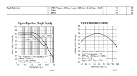
I only see 75 dB ripple rejection in the datasheet you linked ... ???I suggest looking at the LT3080. I ... have found LT's claims of 120 dB ripple rejection to hold up in real life!
Attachments
I'm interested in this thread as I have a modified 1A Velleman PSU based on the LM317 which I am looking to upgrade as a little learning project. I use it to power an SSD in my music server from regulated 12V input. The PSU currently has a 10uF cap on the adjustment pin as shown in the LM317 data sheet (although I note it doesn't have the diode to discharge this cap).
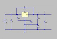
I take it that using a TL431 will yield a better result than the 10uF cap configuration? Am I right to summarise that the conclusion is that shifting the TL431 cathode resistor (R3 in the original post) to the output of the LM317 increases complexity significantly because of the required compensation and so I should stick to the input configuration? Is D6 necessary? Lastly, is there any benefit to using an Onsemi NCP431 which I believe is an upgrade to the TL431? (I have searched for TL431 with ED suffix to no avail so far having found just A and B versions.)
(I will have to figure out how to make the mods given the existing PCB traces but I guess that shouldn't be too hard.)
One way to analyze this is to plot impedance vs. frequency, for a TL431 and also for a 10uF capacitor, on the same graph. If one of the two curves is lower than the other at all frequencies, it's a very easy decision. If not, (i.e. if the curves cross each other), then there's probably room for subjective human judgment to decide "which of these do I like best"?I take it that using a TL431 will yield a better result than the 10uF cap configuration?
I'm interested in this thread as I have a modified 1A Velleman PSU based on the LM317 which I am looking to upgrade as a little learning project. I use it to power an SSD in my music server from regulated 12V input. The PSU currently has a 10uF cap on the adjustment pin as shown in the LM317 data sheet (although I note it doesn't have the diode to discharge this cap).
I take it that using a TL431 will yield a better result than the 10uF cap configuration? Am I right to summarise that the conclusion is that shifting the TL431 cathode resistor (R3 in the original post) to the output of the LM317 increases complexity significantly because of the required compensation and so I should stick to the input configuration? Is D6 necessary? Lastly, is there any benefit to using an Onsemi NCP431 which I believe is an upgrade to the TL431? (I have searched for TL431 with ED suffix to no avail so far having found just A and B versions.)
(I will have to figure out how to make the mods given the existing PCB traces but I guess that shouldn't be too hard.)
I would stick with the input version, much simpler and safer to use.
But put a cap between Cathode and Vref, 1-10uF is a good value, it helps with noise, especially low frequency noise.
TL431ED is the model I have used in my simulation, it is an improved version that follows the TI TL431 datasheet better than other available models.
You could go with the Exar SPX2431AM, it is similar to the TL431 but with significantly reduced noise compared to the standard TL431
Standard TL431 is around 120nV/hZ at 1K and the SPX2431AM is 40nV/hZ at 1K.
The NCP431 looks to have around 600nV/hZ at 1K according to the dataheet, that is downright terrible.
Surely that must be an error?D6 is there in case you short the input to the regulator, if that happens the output capacitor will discharge into to output of the regulator, potentially destroying it.
Last edited:
I would stick with the input version, much simpler and safer to use.
But put a cap between Cathode and Vref, 1-10uF is a good value....
I would go you could go with the Exar SPX2431AM....
D6 is there in case you short the input to the regulator...
Thanks. By chance have you modeled this versus the LM317 + 10uF cap to ground config? (A cheating response to Mark's comment else I would to wait to get home to London, find a model for the TL431 and try out my Spice modeling again.)
Just to clarify the 2nd point (I'm a newbie to this stuff) you mean a cap between cathode and the LM317 adj pin, right?
Thx
Another thing missing on the Velleman module... Btw it started life with a diode rectifier. I removed 3 of the diodes and jumpered one to ground because I have DC input leaving just one LN4007 diode in series with the +ve input. I understand this diode is limited to 1A while the Lm317 can handle 1.5A or more and so the diode is a bottleneck. Can you recommend a better replacement for this? (I'm sure an SSD doesn't use much current but I may want to power two.)
I meant a cap between Tl431 cathode and Tl431 Vref.
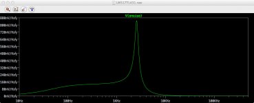
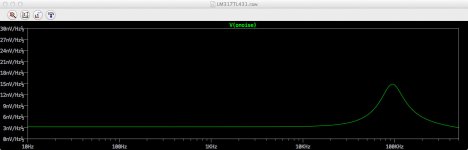
Coming back to this…Have I misunderstood you re the above as I am getting some not-so-great noise results. It would be better without C2. (Targeting 5V.) This is using the model for TL431 recommended by Helmut Sennewald on the LTspice forums.
Attachments
Last edited:
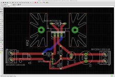
One thing I find puzzling is that I thought a ground or copper pour was meant to "blanket connect" all points connected to ground into the ground pour. But it seems the GND connected traces remain as such.
Attachments
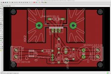
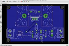
Hi. I named the pour but I didn't name any traces…but when I click on the ground trace running along the bottom it seems to already be named GND (consistent with the pour)
EDIT: okay I see now that I thought I had named the pours but I hadn't. Now fixed. Thanks!!
EDIT: okay I see now that I thought I had named the pours but I hadn't. Now fixed. Thanks!!
Last edited:
A question about ordering some LM317… When I search Mouser for LM317 in TO-220 package 1.5A I still get 15 potential parts. I see that some have slightly better line regulation but others look largely identical except for price but I must be missing something. For a fixed 5V application which would be best?
LM317 to-220 Voltage Regulators - Standard | Mouser
Even narrowing the search to the best line regulation 0.01% yields 3 to choose from
http://uk.mouser.com/Semiconductors...=1z0wadvZ1z0sfwl&Keyword=LM317+to-220&FS=True
LM317 to-220 Voltage Regulators - Standard | Mouser
Even narrowing the search to the best line regulation 0.01% yields 3 to choose from
http://uk.mouser.com/Semiconductors...=1z0wadvZ1z0sfwl&Keyword=LM317+to-220&FS=True
... PSU based on the LM317 which I am looking to upgrade as a little learning project. I use it to power an SSD in my music server from regulated 12V input.
Since a regulated 12V DC supply is connected to its input, the LM317 will not be called upon to perform "line regulation" and so this specification is not relevant in the end application.I see that some have slightly better line regulation but others look largely identical except for price
Additionally, if SSD means "solid state disk", that is a dense array of digital integrated circuits (flash memory chips and controller ASICs), with spectacularly excellent power supply noise rejection compared to typical analog circuitry in audio applications. An SSD neither requires, nor benefits from, ultra tightly regulated supply voltage.
I recommend making a list of the LM317 devices whose package metal tab is thickest (for best heat transfer) and then purchasing the cheapest of those, or most widely available, whichever is most important in your opinion. The datasheets from ST Microelectronics are very good at calling your attention to metal tab thickness, and letting you know the different thicknesses they offer. With other mfrs you gotta dig a bit.
Thanks Mark. I will take a look.
There is a long thread on Computer Audiophile whereby people are professing the "huge benefits" of powering their SSD via batteries independently of the mobo. Personally I am skeptical although there are a number of people whose views I would ordinarily respect stating this. Perhaps they are all suffering from perception bias. I have never tested this as when I put my audio server together I powered the SSD immediately with the Velleman 1A LM317-based module (tweaked to simply remove the rectifier diodes and trimmed to 5V) which in turn is supplied 12V.
There is a long thread on Computer Audiophile whereby people are professing the "huge benefits" of powering their SSD via batteries independently of the mobo. Personally I am skeptical although there are a number of people whose views I would ordinarily respect stating this. Perhaps they are all suffering from perception bias. I have never tested this as when I put my audio server together I powered the SSD immediately with the Velleman 1A LM317-based module (tweaked to simply remove the rectifier diodes and trimmed to 5V) which in turn is supplied 12V.
Last edited:
- Status
- This old topic is closed. If you want to reopen this topic, contact a moderator using the "Report Post" button.
- Home
- Amplifiers
- Power Supplies
- LM317+TL431, really?