Can you be more specific as to what really well constitutes?
When you are more specific about this;
All of the implementations Rod hosts are also noisier than necessary
Want a rock, eh? Lowest noise occurs when feedback impedances are balanced and small. That also maximizes resistor heating and hence distortion from thermal tracking errors. The optimum varies with resistor TCR, C/W delivered by the resistor package and PCB layout, op amp selection, signal levels, and acceptable levels of distortion. But it's generally resistors of 10k or below, either due to good TCRs in surface mount thin film resistors or the lower C/W of leaded parts. All circuits in projects 51 and 87 either fail to balance feedback impedances, use impedances over 10k, or both. This is mitigated by TL07x's low current noise but one could lower the noise floor by probably around 5dB changing over to 10k resistors and NE5532s. That's a reduction of a few microvolts over the 20Hz to 20kHz audio band, a couple of which come back if one changes over more performant parts such as the AD797, LME49720, or LME49990, so don't go thinking it's a big deal. Well, unless one's actually trying to reveal a DAC's noise floor or such (in which case the LME49880 and, interestingly, LME49723 can be attractive).
Your turn. Again.")
Your turn. Again.
Last edited:
Thanks for all the comments on this chaps. To be fair to Rod his line transmitter/receiver project seems to be pitched at achieving a practical balance between performance and simplicity, which is largely why I chose them, so its probably to be expected that there are higher-end solutions. But such things are most useful to know about for potential future tweaks and upgrades so thanks again.
One good thing is that my satisfaction in the line drivers/receivers will be based purely on my own perception, so I should easily be able to tell if I want to upgrade or not. In particular I don't want to hear any noise induced by them from my listening position, and I don't want any noise to be particularly noticeable from other/closer seats within the room either, though I would tolerate a little unintrusive noise there. Abs' experience with them and Rod's reputation encourage me to think perhaps these aspirations aren't unreasonable, although frankly I'll be surprised if my amps etc aren't a much worse limiting factor, at least in the first iterations.
Cheers
Kev
Last edited:
Nah, if that was the design goal they'd knock 10 cents off the quantity 1 receiver BOM by using a part built for the purpose to get higher performance with less soldering. There are several higher cost options beyond that which add performance, too. Some pin compatible, some not.To be fair to Rod his line transmitter/receiver project seems to be pitched at achieving a practical balance between performance and simplicity
For the transmitter there is a cost riser to use a line driver. Starting about USD 1.10. On a board which sells for USD 15. Two extra pins do have to be soldered (le gasp!
) but pick and place is reduced by four parts. So performance up, complexity down, reasonable ROI. As with receivers various options exist to add performance by adding cost.So if ESP wanted to there's not a exactly a shortage of turnkey options which keep the total board + parts BOM under USD 20 for each project at noticeably better performance and reduced assembly labour. There are parts over USD 5 too but a small complexity increase over an board solution would be involved to hit their specs on a separate board. DIYers buy on headline specs rather than actual performance, though. I'm sure simpler, underperforming boards would sell too.
Last edited:
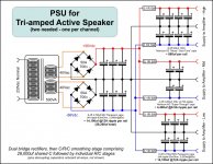
Getting back to the original subject of the thread, attached is a diagram of the PSU configuration that I've finally settled on.
I decided to take advantage of using different amounts of capacitance for the low, mid and high amps to get some decent audio-grade caps on the mid range amp (as well as the high); affording that has necessitated a slight reduction in overall capacitance, but the mid range is particularly important to me so it seems a worthwhile trade-off. I also found the small caps for the tweeter amp were quite cheap (by comparison) so I've gone for a few more of those. The bass amp has standard-spec capacitors in order to afford a reasonable total capacity, but I'm fairly happy with them; they seem respectable for ripple and ESR and their life expectancy is pretty good.
One thing I'm wondering though, is if it would be a good idea to isolate the smaller second C stage of the mid and high amp supplies with diodes (as well as just the R's), i.e. to ensure they won't get drained by the bass amp/driver?
Cheers
Kev
Attachments
It depends on what's going on. For any given situation where CRC, CLC, and diode isolation improve performance there's another where they can make things worse. What are your crossover points and slopes, driver efficiencies, and idle current draw per channel? (The public docs for project 101 mention 5mA for VAS but not the output stage bias.)
I think the law of diminishing returns operates here. Unless you will be operating the system at close to full power, and even then I doubt it, there is plenty of capacitance for even the most base heavy tracks.One thing I'm wondering though, is if it would be a good idea to isolate the smaller second C stage of the mid and high amp supplies with diodes (as well as just the R's), i.e. to ensure they won't get drained by the bass amp/driver?
Abs
I wasn't going to bother, given the nature of your posts, but since Kev is the one who will benefit, I reconsidered.Can you be more specific as to what really well constitutes?
I installed a balanced driver (P87) on one channel and compared it to the unbalanced on the other channel. The unbalanced had a lot of noise and hum while the balanced side was noise free; I certainly couldn't hear any even with my ears close to the drivers. I then installed a balanced driver to the second side and the noise and hum in that channel disappeared as well.
Well, there is a business opportunity for you; put your gratuitous advice to good service for the DIYers and make a dollar as well. It can't be THAT hard, can it?So if ESP wanted to there's not a exactly a shortage of turnkey options which keep the total board + parts BOM under USD 20 for each project at noticeably better performance and reduced assembly labour. There are parts over USD 5 too but a small complexity increase over an board solution would be involved to hit their specs on a separate board. DIYers buy on headline specs rather than actual performance, though. I'm sure simpler, underperforming boards would sell too.
One rock is more than enough when glass is involved.Constructive discussion's welcome if it's chosen. But delivery of one rock's my limit.
More palatable but less accurate, and certainly no improvement.I do agree the redacted version of post 44's an improvement over what went out in email.
Thanks chaps - the extra diodes are probably a bad idea then; I'll build it without any and later just check whats happening with the voltage across the mid and tweeter amp's second stages just to reassure myself.
Thanks also Abs - if you can't hear noise 'that' close to the speaker then its very encouraging; noise was my only real reason for going with the balanced line approach so I doubt I'll want to upgrade any time soon (or ever) if they perform that well for me too - its better than I was really expecting. Previously I've not needed anything more than unbalanced interconnects, but with these active speakers the signal lines will now be quite long and the subsequent amps will always be on fully/unattenuated so I think its worth the extra effort, especially as cable routing will need to lean towards aesthetic rather than electrical considerations.
Cheers
kev
Kevin, what Abs is saying is "a lot" of noise and hum in his (her?) system is reduced to inaudibility by the 40dB typ CMRR of the ESP boards with the amps at idle and therefore minimum ground bounce. This is a majority but not 100% case in both home and pro audio. It's also one reason why post 46 inquires as to bias current.
Kev.
What I said was this;
I am not a glove puppet for someone who lives in fantasy land, despite their self proclamation as "the Old Ones or the Wise Ones".
Maghuin Dhonn - Kushiel's Legacy Wiki
Alba - Kushiel's Legacy Wiki
What I said was this;
I could clearly hear hiss and hum from one channel and not the other. When the second channel was changed, the previous noises were not present.I installed a balanced driver (P87) on one channel and compared it to the unbalanced on the other channel. The unbalanced had a lot of noise and hum while the balanced side was noise free; I certainly couldn't hear any even with my ears close to the drivers. I then installed a balanced driver to the second side and the noise and hum in that channel disappeared as well.
I am not a glove puppet for someone who lives in fantasy land, despite their self proclamation as "the Old Ones or the Wise Ones".
Maghuin Dhonn - Kushiel's Legacy Wiki
Alba - Kushiel's Legacy Wiki
Post 49 perhaps?It's also one reason why post 46 inquires as to bias current.
Last edited:
Thanks for the clarifications, always good to be sure
Twest, sorry, I completely missed the second part of post #49 at the time. My crossover points are still to be determined based on how the drivers actually perform in the enclosures and waveguides, but IIRC my expectations were that they'll probably be something around 300hz and 2.5-3khz. I'm initially going to try 24db/octave crossovers, but I'm likely to also test others in the future so they could change - its fairly unlikely that I'll go below 2nd order though.
The amp's bias currents too will be adjusted during the actual implimentation, but I'd estimate the mid-range amp is likely to be around 20mA, the tweeter's amp could be similar but 'may' be more if I decide to try optimising the 'A' of the 'AB' (but I haven't read up on that yet). The bass amp is likely to be something like 50mA or so, as I'm tempted to build it with two pairs of mosfets, although thats not strictly necessary if the extra bias current introduces problems.
Cheers
Kev
Last edited:
I find +-58.5Vdc from a 40+40Vac transformer.
The absolute maximum during worst case conditions is always >63Vdc even with the mains supply at 254Vac.
I use 63V capacitors.
I recommend you try listening and/or measuring the bass channel performance (in comparison to the other frequency channels) with the 3pr of 4m7F and 4pr and 5pr in that last stage of the rCRC.
big OOPs. ignore the > in post 57
I find +-58.5Vdc from a 40+40Vac transformer.
The absolute maximum during worst case conditions is always less than 63Vdc even with the mains supply at 254Vac.
I use 63V capacitors.
I recommend you try listening and/or measuring the bass channel performance (in comparison to the other frequency channels) with the 3pr of 4m7F and 4pr and 5pr in that last stage of the rCRC.
Last edited:
Thanks Andrew. Perhaps I've been slightly over-cautious with going for 80v caps as a minimum then. The 100v caps are only that voltage because I couldn't find 80v ones, but perhaps there would have been cheaper 63V alternatives if i had looked for them. Oh well, i guess at least its better than being under-rated!
Thanks also for the thoughts on listening/testing various amounts of capacitance on the bass amp's supply. I guess it could actually affect all channels if its deficient, so that makes great sense. After all this expense and effort I wouldn't want it to suffer for the sake of a few more caps, especially as they aren't premium/audio ones on the bass amp's supply.
Cheers
Kev
Grid protection devices tend to trip at 20 to 30% overvoltage so the 20% margin used in post 1 of this thread is arguably a little conservative. Depending on mains THD, diode drops, exact trafo output voltages, loading, and such a 63V cap on a 40V trafo provides about 10% overvoltage margin whereas 80V offers a robust 40% margin. Transient overvoltages (AKA surges or spikes) can easily exceed this, though not normally for more than a couple mains cycles. There's an abundant power quality literature on consumer device reliability in this area one can consult. I usually try to design to 25%, though temporary overvoltages (nominally, mains 10% or more above nominal for one minute) are relatively uncommon.
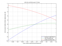
The attached figure shows the relative driver power consumption in the class B range of the AB biasing scheme. As the proposed bias currents are relatively low this is likely representative of the majority of the time music is playing through the system. Post 56 doesn't mention the drivers' passband efficiencies so I used some typical closed box values. The x axis of the plot is essentially a genre axis. The left side is a power spectral density of 1/f, which is typical of classical music, and the right is 1/sqrt(f), which is typical of hard rock and metal. Since the amplifiers on all three channels are identical---and therefore have the same typ PSRR---the capacitance configuration which yields the highest SFDR in relation to power supply artifacts on the output is the one in which the relative capacitances match the relative driver power.
Since the relative driver power likely varies by oh, call it something over 10dB, depending on genre, driver selection, speaker design, crossover points, crossover type, and the particular passage of music playing there's arguably no well defined optimum. However, the configuration proposed in post 48 offers relative capacitances of -27, -13, and -3dB for the tweeter, mid, and woofer, respectively. If the assumption of closed box design above holds it's therefore likely substantial reallocation capacitance towards the tweeter and mid would be a better use of budget.
The maths for this analysis are simple---just a trapezoidal numerical integration of the crossover transfer function times the spectral density plus some normalization. Kev, PM me your email if you want the source code to play around with. It's my suspicion that especially operating points over on the right side of the chart would end up with higher SFDR if the channels all drew from a single cap bank rather than four banks separated by resistors. Taking a look at that in Spice will have to wait for another day, though.
Attachments
- Status
- This old topic is closed. If you want to reopen this topic, contact a moderator using the "Report Post" button.
- Home
- Amplifiers
- Power Supplies
- Power Supply for tri-amped speaker