Hi All,
I have a question on snubber network to damp ringing in a transformer. I've seen most of the threads and articles trying to find the "optimal" value for snubber capacitor and resistance to obtain a "optimal" damping factor of the ringing (with RC snubber or CRC snubber). Why not to use a brute force approach and, given a capacitor value, find the maximum value of resistance allowed by power dissipation on the resistor itself of the RC series snubber network? Is there any drawback in this approach?
As an example and given the power dissipation formula of the resistor in this great article (http://www.hagtech.com/pdf/snubber.pdf), with a 0.1 uF capacitor and 70V RMS@120Hz on the output of the transformer secondary, the power dissipated on the resistor is:
P= R*(Vrms*2*3.14*f*C)^2 = (2.8E-5)*R
which gives me, for a 0.8W resistor:
R < 28K Ohm
which is much much bigger of the optimal values usually calculated (in the range of 100 ohms), and that will make for sure an over damped system. Not using a so big resistor, what if I use a 5K/10K ohm resistor? (I'm actually using 470 ohm resistor with quasi-unaudible buzz…but still is there)
Thanks in advance for your responses and thanks to Mr.Pass for giving me the ideas and tools to enjoy diy audio. Should my question be stupid/non sense/obvious sorry for wasting your time.
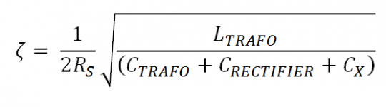
As the value of the damping resistor Rs increases, the damping factor zeta decreases:
 Unfortunately it is easy to create an underdamped, oscillatory RLC circuit with (zeta < 1.0): simply make Rs too big.
If your goal is to make an overdamped RLC circuit, with (zeta > 1.0), the equation suggests decreasing the value of the damping resistor Rs. Just be sure that the capacitive reactance of the snubber's series capacitor Cs, is at least 10X lower than Rs, at the RLC's natural frequency omega_n. 25X lower would be even better.
. .
Attachments
As the value of the damping resistor Rs increases, the damping factor zeta decreases:
Unfortunately it is easy to create an underdamped, oscillatory RLC circuit with (zeta < 1.0): simply make Rs too big.
. .
Hi Mark,
thanks for you're answer. My idea is to have a very low damping factor by increasing Rs, so that we have no oscillation (= no buzz on the trasformer). Maximum value for Rs would be constrained only by power dissipation of Rs itself.
From your answer it seems that having a low damping factor is not good, but would you please explain me why? Is there any other effect on the power supply I'm not considering?
have you checked your "lots of decimal places" yet?
Hi Andrew,
yes I did it....did I make a mistake?
As the value of the damping resistor Rs increases, the damping factor zeta decreases:
Unfortunately it is easy to create an underdamped, oscillatory RLC circuit with (zeta < 1.0): simply make Rs too big.
If your goal is to make an overdamped RLC circuit, with (zeta > 1.0), the equation suggests decreasing the value of the damping resistor Rs. Just be sure that the capacitive reactance of the snubber's series capacitor Cs, is at least 10X lower than Rs, at the RLC's natural frequency omega_n. 25X lower would be even better.
. .
Hi Mark,
sorry for the last answer...I see your point now. From the equation you posted:
- by increasing Rs -> oscillation increase
- by diminishing Rs -> oscillation decrease
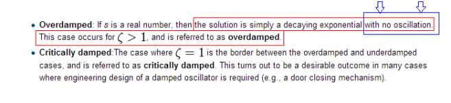
It's been my experience that (Wikipedia's article about the damping ratio) has matched experimental results in the real world. Here's a small portion of that article:

Maybe the appendices of (the Quasimodo design note) might shed some additional light.
Maybe the appendices of (the Quasimodo design note) might shed some additional light.
Attachments
28000 * (70V * 2 * 3.142 * 50Hz * 0.0000001F)² = 0.135W (50Hz) or 0.2W (60Hz)P= R*(Vrms*2*3.14*f*C)^2 = (2.8E-5)*R
The harmonics produce more heating in the resistor relative to their level because the impedance of the cap is lower at the higher frequencies. Fortunately the harmonics of the fundamental are low in level relative to the fundamental.
All this falls apart because this simple calculation ignores the phase.
If you want a simple way to reduce RFI from your power supply, just place a .1uf stacked film cap across the secondary of your transformer. You really don't need a resistor in series with it, you could use a small value like .5-2 ohms if you like.
To see the effect of the cap, place a battery powered AM radio next to your power transformer and tune it to the low end of the band where there is not a station, and listen without the cap, and then with the cap. You will hear the buzz go away with the cap.
To see the effect of the cap, place a battery powered AM radio next to your power transformer and tune it to the low end of the band where there is not a station, and listen without the cap, and then with the cap. You will hear the buzz go away with the cap.
The capacitor retunes the oscillation frequency.
The capacitor rarely makes the buzz go away.
The resistor is the snubber and it is the resistor that damps out the oscillation by absorbing some of the energy.
The only way to find out for sure is to TEST the installation for instability using the correct equipment.
The capacitor rarely makes the buzz go away.
The resistor is the snubber and it is the resistor that damps out the oscillation by absorbing some of the energy.
The only way to find out for sure is to TEST the installation for instability using the correct equipment.
Hi Mark,
Rs -> oscillation decrease
[/LIST]
Just still don't understand how your equation works...if I set Rs very low (as low as zero) I should have a very high (infinite) value for the damping factor with no oscillation at all, and this is not the case whit a pure LC circuit (R->0). Am I still missing something?
An LC will oscillate at a set frequency. It is the resistor that damps this.
I use snubbers a lot in class d and SMPS.
Usually the resistors are sub 22R and sometimes as low as 10ohms or 1 ohm.
I have been playing a little with the Quasimodo-circuit, and it works beautifully. Honestly, I am really impressed with this little tool.
I used it the way Mark Johnson (and Hagerman) recommends and I got R-values between 8 Ohms and 125 Ohms for different transformers IIRC. In other words, I don´t think that one can say that the best solution is just to use a "low R-value" together with a small film cap??.
When designing small snubber-circuits I am very careful, and the Quasimodo has totally removed the guess-work. No calculations and values as "per routine" - no, on the scope one can see exactly what is happening.
Sorry, I have to admit that I have not had the opportunity to try-out the AM Radio trick. It could be fun to try one day. Though, I think that (at least) one of the caps in the CRC-snubber will help catch the high-frequency noise.
Mr. Miller suggests to use another film cap right before the first cap in the cap bank. Hm, I am not quite sure that I will follow this suggestion. If using a small film cap I would suggest to place it between the cap bank and as close to the amplifier circuit as possible to avoid the L in the wires/PCB between the cap bank and the amplifier circuit. This practice is also suggested by Tom Gootee.
Karsten
Far better to fit the local decoupling at the amplifier.The .1 across the big elect is to bypass it at high frequencies, where the elect becomes inductive, and the .1 can short out any remaining RFI. Another .1 close the amplifier is a good idea.
Extra capacitance at the wrong end of a pair of wires is useless at the "high frequencies" you are talking about.
Design in properly located MF and HF decoupling and forget about capacitor bypasses at the PSU.
I have seen a lot of power supply designs with a film cap across the big elect filter cap to bypass it at high frequencies. High freq. noise coming out of the diode bridge is shorted out by the film cap. Try it with, and without, and see which way sounds the best.
And always have local decoupling at the active stages.
And always have local decoupling at the active stages.
Last edited:
Have a look at the link below. Pay attention to the comments and tests made by DIY Audio member Eva.
Karsten
http://www.diyaudio.com/forums/power-supplies/126697-bypassing-psu-capacitors-effective.html
Karsten
http://www.diyaudio.com/forums/power-supplies/126697-bypassing-psu-capacitors-effective.html
- Status
- This old topic is closed. If you want to reopen this topic, contact a moderator using the "Report Post" button.
- Home
- Amplifiers
- Power Supplies
- Overdamping RC snubber network