I've had awesome help from user Elvee designing a new high voltage regulated PSU for my tube poweramp project. Details here: http://www.diyaudio.com/forums/power-supplies/242624-ccs-zeners-resistors-450v-reference-6.html
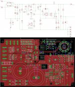
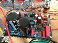
Well, it has taken a while to get everything ordered and build. Had another project creep in, but I finally got to building the HV PSU (see pic and schematic below. PCB includes heater, bias supply and PI as wel).
Although I breadboarded everything extensively, I was first confronted with a 100Hz signal imposing itself on the output when current draw got over 120mA. I suspect(ed) a layout/grounding issue. I have removed the short circuit protection and I also realized I created a ground loop around the MOSFET, which I killed by cutting a slit in the groundplane at one side. The 100Hz is gone now, but I feel it's more dumb luck than actual knowing what was going on. Any tips are welcome, specially on PCB layout.
I'll continue on teseting under more load and hope to get some sound going through it very soon.


Proficiat!I've had awesome help from user Elvee designing a new high voltage regulated PSU for my tube poweramp project.
Having a "sea of copper" as ground is not the best of ideas, as you already noticed: you cannot control how the charging pulses from the filter caps disperse into other areas of the ground.Any tips are welcome, specially on PCB layout.
You should have a direct connection from the rectifier to the filter caps, with nothing else, and from the filter cap, you go to the rest of the circuit, preferably trying to respect the way it is drawn. That way, you'll minimize the ripple and the output impedance.
Indeed, but surprisingly it will also work in this configuration. And even more surprising, it would make D105 redundant...Q103 emitter and collector should be swapped.
Thanks for the replies.
@DUG: If there was a smiley hitting himself with a DMM, I'd post it. Thanks for noticing. One of those errors that creepes in. I'll solder the SS protection back in to see if that's the root of the problem, or if the groundloop issue is (was) to blame
@Elvee: The more knowledge I gain about PSU's and PCB layouts in general, the more I see your point about groundplanes. How the unpredictability of current flow can reaaly screw you up. The next PCB revision will have seperate tracks instead of a groundplane.
I don't really get how Q103 negates D105. I thought D105 was there to prevent the GS junction from over-voltage, 15V in this case.
In any case it recon Q103 should be the other way round I guess(?)
Indeed, but surprisingly it will also work in this configuration. And even more surprising, it would make D105 redundant...
The base emitter "zener" is usually 5-7V.
Yes it would work.
But...
I would not do it this way.
Q103 works at a β<<1, and modern planars have a reverse breakdown more in the 6.5 to 10V range but even so it is preferable to put it right, since it could limit the gate drive in case the MOS is severely undersizedIn any case it recon Q103 should be the other way round I guess(?)
- Status
- This old topic is closed. If you want to reopen this topic, contact a moderator using the "Report Post" button.
- Home
- Amplifiers
- Power Supplies
- High voltage PSU build thread