Hello
I have Started modding an old pc power supply to use it with car amplifiers and for cb, ham radio usage.
Modding it for 13,8 Volts output and need some help from someone more experienced about this mod.
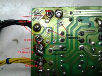
I used two resistors for voltage divider between the 5v and 12v rails and managed to get 13,8v at output.I remouved the coil and capacitor between the 5v rail output but a sound comes from the transformer if i am not wrong and one resistor is getting little hot.
Did not test it with any load yet
Resistors i used was 18 Ohm 5w and 8 Ohm 5w.
Could anybody suggest any idea what else can i do or what causes the sound ?
I have Started modding an old pc power supply to use it with car amplifiers and for cb, ham radio usage.
Modding it for 13,8 Volts output and need some help from someone more experienced about this mod.
I used two resistors for voltage divider between the 5v and 12v rails and managed to get 13,8v at output.I remouved the coil and capacitor between the 5v rail output but a sound comes from the transformer if i am not wrong and one resistor is getting little hot.
Did not test it with any load yet
Resistors i used was 18 Ohm 5w and 8 Ohm 5w.
Could anybody suggest any idea what else can i do or what causes the sound ?
Attachments
Started this mod after reading this page:
Converting Computer Power Supplies to stabilized 13.8 V DC 20 A
The author claims he can draw 20A from it
Why could i not mod it ?
I would be happy with 13.8V 10A (the psu i use is 200W)
Converting Computer Power Supplies to stabilized 13.8 V DC 20 A
The author claims he can draw 20A from it
Why could i not mod it ?
I would be happy with 13.8V 10A (the psu i use is 200W)
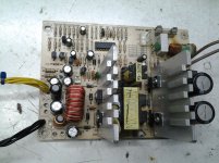
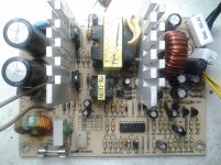
post1 pic1 shows the mains isolation transformer. It's the big rectangular one between the two heatsinks.
That transformer and all to it's right runs direct off the mains !!!!!!!!!
While you are experimenting I strongly suggest you use a separate mains isolating transformer and to keep one hand permanently in your pocket while this thing is powered up.
That transformer and all to it's right runs direct off the mains !!!!!!!!!
While you are experimenting I strongly suggest you use a separate mains isolating transformer and to keep one hand permanently in your pocket while this thing is powered up.
Have a look at the links pic:
big-pc-power-supply-modification.gif Photo by sm5zbs | Photobucket
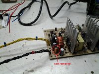
I did not disconnect anything except the two parts mentioned above(coil and capacitor pic 4 first topic)
big-pc-power-supply-modification.gif Photo by sm5zbs | Photobucket
I did not disconnect anything except the two parts mentioned above(coil and capacitor pic 4 first topic)
I know how to protect myself from mains power and i know where the mains power is located on pcb
Thanks for your concern but i didn't ask for safety advice
If you have any helpful ideas for the mod please post them or just ignore it
There is a Prohibition about discussing Line Operated switching power supply electronics on this site. It is obvious that you are modifying a circuit that you do not fully understand. Better just move on.
Is this a helpful Idea ?
You are modding a different power supply, do you have a circuit diagram?
It looks like the idea is to change the voltage fed back to the controller to fool the supply into thinking the voltage is to low thus boosting it a bit to get the 13.8V.
Personally I would get a circuit diagram as a minimum and the data sheet for the controller, then at least you can work out what you are doing.
Though I also think it is not the safest or well thought out mod I have seen.
There is a Prohibition about discussing Line Operated switching power supply electronics on this site. It is obvious that you are modifying a circuit that you do not fully understand. Better just move on.
Is this a helpful Idea ?
What Prohibition ? Are you kiding me ?
Many others have discussed about switching power supply electronics as i searched the forum before posting
It is not allowed to post about switching power supply ?
If there is a problem or prohibition moderator will say it not you.
I will decide the way and how to move on. If you don't like it move on yourself. As i said before ignore the post
The local ham club in Athens probably has a copy of one of the ARRL handbooks from the 2000's -- they have an article describing exactly what you seek to do including details on winding new inductors. Would suggest that this is a better venue.
Thanks. I will search it.
You are modding a different power supply, do you have a circuit diagram?
It looks like the idea is to change the voltage fed back to the controller to fool the supply into thinking the voltage is to low thus boosting it a bit to get the 13.8V.
Personally I would get a circuit diagram as a minimum and the data sheet for the controller, then at least you can work out what you are doing.
Though I also think it is not the safest or well thought out mod I have seen.
Will it help if i take a couple of pics of both sides pcb ?
Hi there,
If you want to modify this power supply to a variable supply and your on board PWM controller is either TL494 or KA7500 i suggest you read all the info in the links below and all you're gonna need is two resistors and a potentiometer and no power resistors. Read em carefully and if you wanna ask anything i will be happy to answer.")
Fully Regulated ATX Power Supply - BOGIN, JR.
PC ATX power supply unit: 18V 400W - RC Groups
Best regards.
If you want to modify this power supply to a variable supply and your on board PWM controller is either TL494 or KA7500 i suggest you read all the info in the links below and all you're gonna need is two resistors and a potentiometer and no power resistors. Read em carefully and if you wanna ask anything i will be happy to answer.
Fully Regulated ATX Power Supply - BOGIN, JR.
PC ATX power supply unit: 18V 400W - RC Groups
Best regards.
What is the controller number, best of start looking for the data sheet for that, there are usually some sort of circuit diagram, if not you can reverse engineer the circuit board to create the circuit for the area of interest.
The controller is: DBL 494
datasheet:
DBL494 pdf, DBL494 description, DBL494 datasheets, DBL494 view ::: ALLDATASHEET :::
Hi there,
If you want to modify this power supply to a variable supply and your on board PWM controller is either TL494 or KA7500 i suggest you read all the info in the links below and all you're gonna need is two resistors and a potentiometer and no power resistors. Read em carefully and if you wanna ask anything i will be happy to answer.
Fully Regulated ATX Power Supply - BOGIN, JR.
PC ATX power supply unit: 18V 400W - RC Groups
Best regards.
Very helpful links you provided sghr220. This will be definitely needed as i understand. I will read them and come back with questions
I don't understand why you are putting the load resistors on the output?
The resistors you need to change,are the feedback resistors from the 12V rail to the controller chip.
From the link friend posted earlier i understand that it is more effective to change some resistors from the controller like you say
I used this resistor for voltage divider. At the link below this guy did it .
Converting Computer Power Supplies to stabilized 13.8 V DC 20 A
Hi there,
If you want to modify this power supply to a variable supply and your on board PWM controller is either TL494 or KA7500 i suggest you read all the info in the links below and all you're gonna need is two resistors and a potentiometer and no power resistors. Read em carefully and if you wanna ask anything i will be happy to answer.
Fully Regulated ATX Power Supply - BOGIN, JR.
PC ATX power supply unit: 18V 400W - RC Groups
Best regards.
I will do the mod from second link fraind posted
From controllers pin1 will be cut from pcb and i will add this circuit : http://boginjr.com/wp-content/uploads/regulpsu.png
The author says :
double-check that the TL494 chip is getting its supply voltage from a “helper” supply. Basically, you should see at least 3 ferrite transformers on the circuit board and a heatsinked linear stabilizer (78xx) powering the chip
I could not find anything from (78xx) powering the chip. Is it ok to add this circuit ?
Maybe from the pic i attached yuo can spot anything ?
Attachments
- Status
- This old topic is closed. If you want to reopen this topic, contact a moderator using the "Report Post" button.
- Home
- Amplifiers
- Power Supplies
- Old Computer Power Supply Mod