This is an adaptation of Rod Elliot's capacitance multiplier. I am filling a couple of needs with this circuit, which will be powering a 500W mono class-D amp into a 4 ohm load.
Since I have a couple of 500VA transformers but the secondaries are a bit too hot for the class-D amp's overvoltage limit I want to be able to limit the maximum voltage that the cap multiplier can produce. I use a set of zeners for this purpose.
Rod Elliot's original design is for a modest output class-A amp, and uses a single darlington for each rail. I am powering a different type of amp, need higher output power and current capabilities. I've used multiple pass transistors in parallel with low R current sharing resistors to help balance the load. I don't have any experience designing and building this kind of thing, but it seems logical to do it this way and I would rather not use a MOSFET. I have also used higher input and output capacitance, 10,000uF per rail, of which I have a few with a sufficient voltage and current rating.
Here is the circuit that I am using to sim the performance of the supply:

This is pretty similar to Rod's circuit, with zeners Z1-Z4 replacing resistors in his circuit, the increased input and output capacitances, and the multiplicity of TIP3055 and TIP2955 devices. I show a 30A bridge but I will use a 50A bridge in the real circuit, mounted on the heat sink.
I see pretty good performance in my simulations under a variety of loads. Under no-load conditions, the zeners form a voltage divider with R1&R2 or R3&R4 and limit the voltage at the base of the BD140 and BD139 transistors. This lets me for instance limit the rail voltages to +/-87V with very low ripple - the first bank of capacitors (C1, C2) is sitting at around +/-92V with the mains at 120VAC and it doesn't change if the mains voltage rises - it's a nice hard limit. With increasing load current being drawn, the output voltage falls along with the average voltage on C1 and C2 and remains only a few volts below the minimum in the ripple. At very high output power (e.g. 600W) the difference increases a bit to about 6V. When I only used a single TIP3055/TIP2955 this was much larger, likely due to the current demand approaching the limit of those devices. This is one reason why I decided to parallel a few of them (four in the circuit as shown). I assume I need low tolerance 0.1R balancing resistors in order to parallel these correctly...
I'd love to get some feedback on this design and where I may be way off, if I am pretty much on target, or any tweaks that might be appropriate.
-Charlie
Since I have a couple of 500VA transformers but the secondaries are a bit too hot for the class-D amp's overvoltage limit I want to be able to limit the maximum voltage that the cap multiplier can produce. I use a set of zeners for this purpose.
Rod Elliot's original design is for a modest output class-A amp, and uses a single darlington for each rail. I am powering a different type of amp, need higher output power and current capabilities. I've used multiple pass transistors in parallel with low R current sharing resistors to help balance the load. I don't have any experience designing and building this kind of thing, but it seems logical to do it this way and I would rather not use a MOSFET. I have also used higher input and output capacitance, 10,000uF per rail, of which I have a few with a sufficient voltage and current rating.
Here is the circuit that I am using to sim the performance of the supply:
This is pretty similar to Rod's circuit, with zeners Z1-Z4 replacing resistors in his circuit, the increased input and output capacitances, and the multiplicity of TIP3055 and TIP2955 devices. I show a 30A bridge but I will use a 50A bridge in the real circuit, mounted on the heat sink.
I see pretty good performance in my simulations under a variety of loads. Under no-load conditions, the zeners form a voltage divider with R1&R2 or R3&R4 and limit the voltage at the base of the BD140 and BD139 transistors. This lets me for instance limit the rail voltages to +/-87V with very low ripple - the first bank of capacitors (C1, C2) is sitting at around +/-92V with the mains at 120VAC and it doesn't change if the mains voltage rises - it's a nice hard limit. With increasing load current being drawn, the output voltage falls along with the average voltage on C1 and C2 and remains only a few volts below the minimum in the ripple. At very high output power (e.g. 600W) the difference increases a bit to about 6V. When I only used a single TIP3055/TIP2955 this was much larger, likely due to the current demand approaching the limit of those devices. This is one reason why I decided to parallel a few of them (four in the circuit as shown). I assume I need low tolerance 0.1R balancing resistors in order to parallel these correctly...
I'd love to get some feedback on this design and where I may be way off, if I am pretty much on target, or any tweaks that might be appropriate.
-Charlie
Hi Charlie.
I am by no means an expert but with this current draw its best to split the bridge rectifier into two; one for positive DC and one for negative DC. The reason being the positive rail or negative rail could draw more current than the other (usually the pos) which cause an imbalance. If your +&- loads are symmetrical then you may be ok.
I am currently soldering up a similar PSU for my amplifier although slightly less current capability. have a look here http://www.diyaudio.com/forums/power-supplies/244796-new-psu-power-amp-2.html I will post details and results once I have finished building in the next few days.
Cheers
Dom
Hi Charlie.
I am by no means an expert but with this current draw its best to split the bridge rectifier into two; one for positive DC and one for negative DC.
The transformer does not have dual independent secondaries, so you can't use two bridges like you do in your PS.
I've done some more simulating and as a result have made some slight changes to the circuit:
I have now included the resistors (labeled as Rdrop) that I previously left out of the circuit that help to drop more voltage to the base of the transistors, increasing the difference between the input and output cap bank voltages for each rail. It works by forming a voltage divider with the resistor Rspeed that forms the filter and is connected to the input caps. I had to put that resistor back in the circuit, because I have taken out one set of the RC filters and have drastically reduced the time constant of the remaining filter from about 0.1 second to about 0.01 second. I made these changes after simulating a rapid change from no-load/idle conditions to high power using the scheme shown in the schematic (time activated lossless "relays" that change the load for about 100msec). I discovered that the filters in Rod's circuit are slow enough that the input cap drains faster than the filtered voltage applied to the base of the BD139/BD140 and the cap multiplier can no longer function properly. Rod warns of this and suggests increasing the voltage drop between the input and output of the cap multiplier, but going overboard with voltage drop will increases the continuous dissipation in the pass transistors.
My approach is to make the single remaining RC filter (formed by Rspeed and Cspeed) time constant fast enough that it can fall as fast as, or faster, than the sag of the average voltage on the input caps under a brief high power demand. This helps to keep at least a couple of volts up between input and output. At the same time I am sacrificing ripple attenuation, but since I am not powering a class-A amplifier the ripple level is still more than acceptable and much better than a cap bank alone. You might be able to get this performance out of an RCRCRC type supply, but then you do not have the overvoltage limit that I get with the zeners, and which is necessary for my application.
The value for Rspeed has been chosen to keep the current flowing through it, and out the zeners, to a relatively low value so that when the zeners are allowing current to pass under no load conditions they will not have to dissipate much compared to their rating (rated 500mW each versus less than 200mW to dissipate between the two zeners).
One consequence of the single faster filter is that the transistors are now trying to charge up the output caps on startup very quickly, resulting in a large but brief "inrush" current through the transistors of more than 30A. I will probably add a startup circuit that will switch in a large resistor in series with Rspeed for the first few seconds to slow the ramp up of voltage and be kind to the transistors. This can be part of a soft-start that will also disconnect a NTC thermistor after a few seconds.
Here is the version 2 schematic:

Below are some sims where the simulated load is changed for 100msec. On the left (or first) is the unzoomed view, and then a view zoomed into the region of action:


In the unzoomed view you can see the inrush surge (in AM1) at startup and the general behavior over the first few seconds. In the zoomed view you get a better feel for what is happening at the cap multiplier input and output rails. Under the sudden demand (about 600-700W, the 365 shown is for one half of the PS) ripple appears across the input cap, Vfiltered, and its voltage sags down to about 81.8V at the bottom of the ripple. The output caps voltage follows the same trend. It's voltage has sagged so that the corresponding peak in the remaining ripple is at about 78.5V. Thus we still have slightly over 3V between input and output which helps the CM continue to function and while there is some residual ripple it is very small and the behavior is more like a gentle rail sag followed by recovery.
The ripple improvement of the CM circuit (ripple on input cap versus ripple on output cap) under a continuous 600W demand is still over 20dB with this circuit. At lower power demand the ripple is very low, and this should work well for the amplifier that I plan on using.
I have now included the resistors (labeled as Rdrop) that I previously left out of the circuit that help to drop more voltage to the base of the transistors, increasing the difference between the input and output cap bank voltages for each rail. It works by forming a voltage divider with the resistor Rspeed that forms the filter and is connected to the input caps. I had to put that resistor back in the circuit, because I have taken out one set of the RC filters and have drastically reduced the time constant of the remaining filter from about 0.1 second to about 0.01 second. I made these changes after simulating a rapid change from no-load/idle conditions to high power using the scheme shown in the schematic (time activated lossless "relays" that change the load for about 100msec). I discovered that the filters in Rod's circuit are slow enough that the input cap drains faster than the filtered voltage applied to the base of the BD139/BD140 and the cap multiplier can no longer function properly. Rod warns of this and suggests increasing the voltage drop between the input and output of the cap multiplier, but going overboard with voltage drop will increases the continuous dissipation in the pass transistors.
My approach is to make the single remaining RC filter (formed by Rspeed and Cspeed) time constant fast enough that it can fall as fast as, or faster, than the sag of the average voltage on the input caps under a brief high power demand. This helps to keep at least a couple of volts up between input and output. At the same time I am sacrificing ripple attenuation, but since I am not powering a class-A amplifier the ripple level is still more than acceptable and much better than a cap bank alone. You might be able to get this performance out of an RCRCRC type supply, but then you do not have the overvoltage limit that I get with the zeners, and which is necessary for my application.
The value for Rspeed has been chosen to keep the current flowing through it, and out the zeners, to a relatively low value so that when the zeners are allowing current to pass under no load conditions they will not have to dissipate much compared to their rating (rated 500mW each versus less than 200mW to dissipate between the two zeners).
One consequence of the single faster filter is that the transistors are now trying to charge up the output caps on startup very quickly, resulting in a large but brief "inrush" current through the transistors of more than 30A. I will probably add a startup circuit that will switch in a large resistor in series with Rspeed for the first few seconds to slow the ramp up of voltage and be kind to the transistors. This can be part of a soft-start that will also disconnect a NTC thermistor after a few seconds.
Here is the version 2 schematic:
Below are some sims where the simulated load is changed for 100msec. On the left (or first) is the unzoomed view, and then a view zoomed into the region of action:
In the unzoomed view you can see the inrush surge (in AM1) at startup and the general behavior over the first few seconds. In the zoomed view you get a better feel for what is happening at the cap multiplier input and output rails. Under the sudden demand (about 600-700W, the 365 shown is for one half of the PS) ripple appears across the input cap, Vfiltered, and its voltage sags down to about 81.8V at the bottom of the ripple. The output caps voltage follows the same trend. It's voltage has sagged so that the corresponding peak in the remaining ripple is at about 78.5V. Thus we still have slightly over 3V between input and output which helps the CM continue to function and while there is some residual ripple it is very small and the behavior is more like a gentle rail sag followed by recovery.
The ripple improvement of the CM circuit (ripple on input cap versus ripple on output cap) under a continuous 600W demand is still over 20dB with this circuit. At lower power demand the ripple is very low, and this should work well for the amplifier that I plan on using.
Note about inrush through transistors mentioned above:
If a soft-start is used on the primary side of the transformer, it limits the charging of the caps on the input side of the CM circuit so that the transistor inrush current is limited to 5-10A, and this is within what the transistors can handle. No need to add an extra element to the CM filter after all - the circuit will work just fine.
If a soft-start is used on the primary side of the transformer, it limits the charging of the caps on the input side of the CM circuit so that the transistor inrush current is limited to 5-10A, and this is within what the transistors can handle. No need to add an extra element to the CM filter after all - the circuit will work just fine.
Here is a version with a soft-start circuit included. I've also grouped and labeled the "control" part of the capacitance multiplier - this could be implemented on a small PCB while the bridge, caps, and main transistors could be bolted to the chassis or heatsink.
Schematic:

Here is the sim of the startup:

The soft-start resistance keeps the mains inrush current down to about 8A or less. This also helps the inrush through the transistors, which are trying to power up the output caps of the CM, to a couple of amps or less.
Power to the soft-start circuit is supplied using an auxiliary transformer, bridge, and smoothing cap that is then regulated to 12Vdc using an LM7812. This supply runs a 555 timer circuit, which directly drives a relay that bypasses the soft-start resistance element(s) after a few seconds.
I would use a couple of NTC thermistors in series rather than power resistors in the actual application of this circuit.
Schematic:
Here is the sim of the startup:
The soft-start resistance keeps the mains inrush current down to about 8A or less. This also helps the inrush through the transistors, which are trying to power up the output caps of the CM, to a couple of amps or less.
Power to the soft-start circuit is supplied using an auxiliary transformer, bridge, and smoothing cap that is then regulated to 12Vdc using an LM7812. This supply runs a 555 timer circuit, which directly drives a relay that bypasses the soft-start resistance element(s) after a few seconds.
I would use a couple of NTC thermistors in series rather than power resistors in the actual application of this circuit.
I've made some more changes to the circuit. I'm using different output transistors and now have only a pair for each rail for 500VA level, and even that is overkill. The transistors don't see all that much dissipation because the voltage drop from collector to emitter is always low. With the integrated soft start, the performance seems very good and the ripple rejection is over 40dB now.
I'd like to make up a PCB for the control circuitry. I'm wondering if I should keep the power transistors off of the board and wire point to point (allows for heavier gauge wire) or move them on to the board and use wide PCB tracks. Keep in mind that the current flowing through the PCB traces might be as high as 5A continuous under high demand. This seems a little much for a PCB...
I'd like to make up a PCB for the control circuitry. I'm wondering if I should keep the power transistors off of the board and wire point to point (allows for heavier gauge wire) or move them on to the board and use wide PCB tracks. Keep in mind that the current flowing through the PCB traces might be as high as 5A continuous under high demand. This seems a little much for a PCB...
Hi,
My only observation is a capacitance multiplier really shouldn't
need that amount of output devices to stay in device SOA.
Adding a small transistor to the drivers to make them CFP's
might help. Using multiple emitter resistors per device, e.g
3 x 0.33R 1W might help, and will improve tolerance.
Douglas Self discusses beta droop of output transistors
at high current in his books, there are better devices
than the 3055/2955 to do the job required here.
( I understand some versions of the 3055/2955 are very poor.)
rgds, sreten.
Last edited:
Hi,
My only observation is a capacitance multiplier really shouldn't
need that amount of output devices to stay in device SOA.
Adding a small transistor to the drivers to make them CFP's
might help. Using multiple emitter resistors per device, e.g
3 x 0.33R 1W might help, and will improve tolerance.
Douglas Self discusses beta droop of output transistors
at high current in his books, there are better devices
than the 3055/2955 to do the job required here.
( I understand some versions of the 3055/2955 are very poor.)
rgds, sreten.
Good idea to use multiple resistors in parallel to improve tolerance of the emitter resistors.
I haven't updated the schematic, but I have replaced the four TIP3022 and TIP2955 with at most two (one is OK) TIP35C/TIP36C which have higher current ratings and are more current devices. Either could work, really. For instance in my sims I see a current load of about 4-5A on the CM transistors under a high power demand. Even a single transistor could handle this.
The transistors are under much less stress in this application compared to a power amp, where the collector-emitter voltage difference is comparable to the rail voltage in magnitude. In this application the voltage drop is much less, for instance here it is about 6V under no load (and thus no current draw) and at higher loads where current draw increases and the rail voltages sag the output rails track the input and stay about 2-3V below. This will limit power dissipation in the devices.
The Beta droop issue can (probably) be avoided by making sure that the transistors are overrated in terms of current rating. For instance a single TIP35C is rated for up to 25A, where as a high demand would be 5A.
So, any thoughts about the layout (on-board or off-board) of the power transistors?
Here is an updated schematic. As I mentioned above I have changed the transistor types and made some other minor modifications.

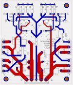
I've done a layout in my PCB layout software, which is attached. Any comments?
The largest (red) tracks are 120-160 mils wide. They should be able to carry a nominal 5A and 90VDC. How thick should these be? Instead of wide tracks, should I use an 80mil track and leave the soldermask off so that additional solder can be deposited on top?
The largest (red) tracks are 120-160 mils wide. They should be able to carry a nominal 5A and 90VDC. How thick should these be? Instead of wide tracks, should I use an 80mil track and leave the soldermask off so that additional solder can be deposited on top?
Attachments
There are many handy online calculators for such estimates. Here is one: The CircuitCalculator.com Blog PCB Trace Width Calculator
It depends on how hot you want the trace to become. If you put numbers in the above calculator (assuming 1oz copper), you will see that to get a 10 Celcius temperature rise you need something like 109 mil fat tracks. A 160 mil track will rise approximately 5 Celsius above ambient, which is very good. A 80 mil track would rise about 17 Celcious above ambient.
You choose, but my guess is that bigger can't harm. 🙂
Updated layout
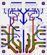
I have made some updates/improvements to the layout.
The fat tracks start out at 160mils where they leave the 5-pin terminal block and taper down to 120mils at the other ends.
Down the center of the power tracks (wide red tracks in the lower portion of the layout) there is now an 80mil wide portion that has no solder mask. This is shown in green. If lots and lots of current will be flowing you can add some solder to these areas to increase the cross sectional area of the conductor and reduce losses/heating. Probably overkill, but its a nice option to have available if you want/need it.
Attached is the new layout as well as a couple of representative views in 3D. The TO247 packages don't show up exactly right, but I made sure that the hole dims and spacing is correct and it is only the 3D model of the part that looks slightly different. I designed the layout using a parts list that I put together for my first build, but they components are completely adaptable to pretty much any audio power supply needs by changing a couple of resistors.
AT this point I an trying to think of where any problems could crop up and I am wondering about where some of the low current tracks cross the high current tracks (red and blue are on opposite sides of the board). Specifically the tracks leading from R11, R20, R12, and R21 to the TIP devices (blue traces in the lower half of the layout). High current means several amperes and low current means several milliamps. Should I put some guard tracks around/along these few tracks, or will it not be important on a power supply board? If currents were induced in the low current tracks could this provide a feedback path so that the circuit might do some unpredictable things under high current demand or oscillate in some way? I'm just playing devils advocate here and trying to think of any gotchas before I fab some of these. If it looks good I would probably shoot for a run of 20 boards which would leave some extras if people are interested.
.
Attachments

A small clarification on this project:
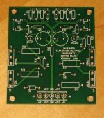
The PCB contains the "heart" of the capacitance multiplier power supply - the RC filter, voltage limiting zeners, and transistors arranged in a Darlington to dole out current from the input side to the output side. Additional off-board components are needed to complete the power supply.
The other components that are necessary are at least FOUR large capacitors, a transformer and bridge rectifier(s), fusing, switch, etc. I use computer grade screw terminal capacitors, which is why I have designed the CM PS with the caps off-board. This approach allows you to use any large reservoir capacitor type you want, as many as you would care to connect together. If you have thru hole caps, you will need to buy or make a board to connect them or wire point to point. Putting the reservoir caps on board takes up a lot of real estate, so this is a way to add versatility and reduce the PCB to only that part of the PS that needs it.
-Charlie
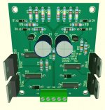
These are now out for production. I ordered 25 boards and should have them back in a couple of weeks time. Size is 3 x 3.5 inches. I will build up a board, test it out, and post the results here.
I wanted to describe some interesting aspects of this project and get some feedback from other forums members.
First, a quick review of linear unregulated power supplies - that is a power transformer, bridge rectifier, and smoothing caps. Under no load the rail voltages are at their maximum and have low ripple. When current is drawn by the amplifier, the capacitors discharge a bit in between the time when they are recharged through the rectifier - this is only happening in "pulses" at the peak of the AC mains waveform. The more current that is demanded by the amplifier the more the capacitors discharge in between each charging pulse and the larger the ripple. At some point the speed at which the capacitors can be replenished becomes slower than the speed at which they are being drained by the amplifier, and the rail voltages "sag". This is the normal behavior of this type of power supply.
For class A amplifiers the ripple on the rails is constantly present at the amplifier output because of a continuous (bias) current demand. One way to reduce the ripply amplitude is to use a very, very high amount of capacitance in the power supply.
Instead of using very large capacitors, you can instead use a transistor to reduce ripple. The base of the transistor is driven by a filtered version of the capacitor voltage and the output of the transistor powers a second set of capacitors. For the transistor to function properly, there must be a voltage drop between the emitter and collector of about 2-3 volts and this is achieved by creating a voltage divider on the filtered voltage that is driving the base. This topology is known as a capacitance multiplier circuit, because there is a relationship between the filter capacitor (driving the transistor's base) and the Hfe (gain) of the transistor such that the product of the gain and capacitance becomes the effective capacitance and this can be made very large via high Hfe, typically using a Darlington configuration or the like.
With just one extra component added to the capacitance multiplier, you can also get some "regulation" under no load conditions. By adding a zener diode you limit the voltage that can be applied to the base of the transistor that is controlling the output voltage. This limits the maximum voltage on the second set of caps, and therefore on the rail voltage.
Now let's think about class AB amplifiers:
In a recent thread someone was describing a power supply that had no-load rail voltages that were too high for the amplifier and output load. The capacitance multiplier with overvoltage limiting circuit can be used to "fix" this situation by choosing a zener with a breakdown voltage that corresponds to the maximum rail voltage for the configuration of the amplifier. Not until the voltage on the capacitors sag sufficiently at high current demand will the rail voltages dip below this level and then they will do it gracefully and without much ripple as a result of the capacitance multiplier topology. This would be a way to solve the problem of "too hot rails" without having to buy a separate transformer. This might be important to DIYers who might be limited by what transformer they can purchase (or get for cheap!).
Let's take the above idea and run with it: you can use a transformer that has secondary voltages that are "too high" and a VA rating that is "too low", and combine it with the CM+OVP circuit. At low/no load conditions, the OVP will keep the rail voltages within safe limits. At higher rail voltages, the rails will sag but ripple on the CM output will be low and because the secondary was "too high" to start with, there is more headroom in the PS to use.
As a bonus, if your mains voltage fluctuates and you want to make sure that the rail voltages do not climb to unsafe levels along with the mains, OVP can fit the bill.
Since transformer VA = $$$, you can spend less on the transformer by adding on a few inexpensive components in the CM+OVP. In the limit of low transformer VA, the conduction angle of the rectifier diodes should increase and this can counteract the low VA because the charge pulses will be longer compared to the no-load or low-load condition when the caps are fully charged or almost fully charged. This will result in large ripple on the first set of capacitors, but the CM action will reduce the ripple by 40dB.
Under this scenario, the voltage differential on the transistors will be increasing and the dissipation rating of the transistors will limit how far this idea can be pushed. Heatsinking the transistors will be required to keep them cool, and the amount of heatsinking required will also need to be factored into the equation.
How is this circuit a "capacitance multiplier"? It appears to be just a regulated power supply with high current capability.
I tried to explain how it works in my last post... sorry if I was not clear.
The behavior is like a regulated supply at no-load and transitions to capacitance multiplier type operation as more current is drawn from the PS.
THIS Google search will provide you with lots of reading material on a CM PS.
The behavior is like a regulated supply at no-load and transitions to capacitance multiplier type operation as more current is drawn from the PS.
THIS Google search will provide you with lots of reading material on a CM PS.
Last edited:
- Status
- Not open for further replies.
- Home
- Amplifiers
- Power Supplies
- a Capacitance Multiplier with over-voltage protection