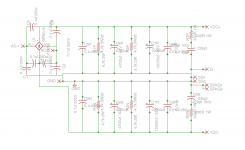
Your schematic is riddled with capacitors that you don't need. Worse, some of them could promote supply rail oscillation.
Thank you for pointing out, I will check and remove some caps.
I've read this app note, and the companion to it and I understand what they are trying to do with this supply. Section 3.1 of AN-1849 describes what the components do and it does explain that you can get away without some of them.
But...this is a reference design. NatSemi wanted to show off their product under the best conditions possible so they went hog wild.
The PSU is over the top but so is the reference design for the amp it's designed to power. Please see AN-1850 LME49830TB Ultra-High Fidelity High Power Amplifier Reference Design. THD+N for the LME49830TB at 10W, 1kHz is <0.0008% with sufficient bias. That's quiet for a class AB amp!
In short, it all comes down to determining the merit of installing $5 worth of caps for a bit less HF ripple on your rails...It's your call. Unless your amp is of similar design caliber to the one in AN-1850 you're unlikely to be able to measure let alone hear the difference.
I wouldn't be so quick to dismiss AN-1849....Bob Pease was still at NatSemi when that was first written and published. He must have seen it; he was in charge of their analog department. That man knew what he was doing; he was a legend in analog circuits.
Finally, these caps will not and cannot cause instability when placed in the power supply as shown in AN-1849. If anything, they'll increase stability by lowering the supply impedance at high frequencies. (the ESL of the large filter caps allows HF to pass by relatively unimpeded until it hits those smaller caps which eat it up)
Last edited:
C1, C2, C5 & C6 are likely to increase the risk of ringing in the PSU.
C5p, C5n, C8p and C8n are likely to increase the risk of ringing in the PSU.
That's 8 capacitors that should be removed.
The snubbers (C9p, R3p,C9n, R3n) at the output are in the wrong place.
Move one of them to across the rectifier ~~. discard the other.
If there are two separate secondaries, then use two snubbers, one across each secondary.

We probably should have AN1849 on hand:based on National (now TI) Application Note AN1849
https://www.ti.com/lit/an/snaa057c/snaa057c.pdf
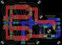
Im looking to buy the PCB if you know anybody who sells such a PCB it would be helpful. Worst case will have to make my own gerber files. If that happens will share it with the community for sure.We probably should have AN1849 on hand:
https://www.ti.com/lit/an/snaa057c/snaa057c.pdf
My Audio Guru has recommended that I start by building a few amps. Using tried and tested designs. This will help in understanding how they work. From the oldest designs to the latest. He says once you have the basics right and understand the schematics then try improving the components. Try all possible combinations. After that trying using different components to see how they impact the sound. If your lucky along the way you will find a setup that you love.In my limited experience 3886 doesnt benefit much from the psu jumping from 4700uf to 9400uf. If youre ok with just one pair of caps the board layout can be far superior
My plan is to have one transformer and one power supply board. Which will take care of all the amps being planed. So I don't worry about that for any of the amps. Im looking at this from an angle of using it on various amps not just the LM. I am sure people have built better circuits. Im sure not all the components are needed. But its a good starting point for me. I have no comercial plans. Lead a comfortable semi retired life. So a extra component here and there will not matter. The inputs are appreciated and will see what helps and what does not once its built. Will keep an eye out for ringing.
In that case i think your idea is sound. Many class ab amps benefit from higher psu capacitance so why not aim for whats highest possible with a reasonable footprint? I think the board you pointed out was designed for that purpose. Its not by and large reference design tho. For that double bridge rectifier should be employed.
- Home
- Amplifiers
- Power Supplies
- LM3886 Power supply based on AN1849