Perhaps glue will adhere a disc of sheet steel the same diameter as the toroid. This disc is dished to a depth greater than the height of the bolt head. Now the toroid is bolted to the steel disc, and the disc glued to the chassis. (This 9 lb, 400VA toroid), for example, would need a disc 13 cm in diameter, and the dishing would be a circle about 3 cm in diameter. The gluing surface is an annulus whose area is Pi x (6.5^2 - 1.5^2) = 125 square centimeters.
Wikipedia says JB Weld's adhesion is 12 MPa, so it can support a weight of 1.2 million kg per square meter of glued area. For the 125 cm^2 disc, that's a weight of 15,000 kg. The toroidal transformer weighs 4.1 kg, so the glue is 3700x stronger than necessary to hold the transformer when the chassis is turned upside down. 370x stronger than necessary if the inverted chassis undergoes an acceleration 10 times the force of gravity.
Wikipedia says JB Weld's adhesion is 12 MPa, so it can support a weight of 1.2 million kg per square meter of glued area. For the 125 cm^2 disc, that's a weight of 15,000 kg. The toroidal transformer weighs 4.1 kg, so the glue is 3700x stronger than necessary to hold the transformer when the chassis is turned upside down. 370x stronger than necessary if the inverted chassis undergoes an acceleration 10 times the force of gravity.
Ignore the PS Mark, I found in your note that you recommend EPCOS B32529.
Having read the section in your note relating to soft-recovery diodes, I wonder if you would have any comments in relation to the appropriateness (or otherwise) of the CREE C3D08060A silicon carbide Schottky diodes in this regard.
Also one (naive) question regarding the Quasimodo itself: it uses a 120Hz oscillator; in a 230V 50Hz environment does this matter?
(Have I read the document correctly in that Crectifier is not a discrete component but rather simply the capacitance of the diodes?)
Last edited:
Hmm, each of your secondaries is 15V @ 5.3 amps (math: 2 secondaries * 15V * 5.3A = 160VA for the entire transformer). So you'll want diodes rated for at least 80V and at least 10 amps.
You connect 2 x 22,000uF right after the diodes, so you'll have a large inrush current on the first half-cycle when a diode charges the two input caps all the way from 0V to 19V in 4 msec. I = C * dV/dt = 209 amperes or thereabouts. (Use SPICE for a better estimate). So you'll want diodes rated for VERY large "Non repetitive peak surge current".
I myself certainly would not select or pay for Cree's Silicon Carbide diodes; instead I'd probably choose something like the Fairchild FFPF30UP20S. It's rated for 30 amps, 200 volts, and most importantly, it's an honest to goodness soft recovery diode with the softness parameters (ta, tb) measured and specified on the datasheet. Non repetitive peak surge current is 300 amps. It's way cheaper than the Cree diode too: Mouser has 1129 of them in stock, on the shelf, for $1.24 each in quantity 10 (link)
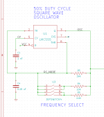
Post #1 of the Quasimodo thread includes a circuit schematic of the thru-hole version V4. I've attached a little snippet from that schematic, below.
You connect 2 x 22,000uF right after the diodes, so you'll have a large inrush current on the first half-cycle when a diode charges the two input caps all the way from 0V to 19V in 4 msec. I = C * dV/dt = 209 amperes or thereabouts. (Use SPICE for a better estimate). So you'll want diodes rated for VERY large "Non repetitive peak surge current".
I myself certainly would not select or pay for Cree's Silicon Carbide diodes; instead I'd probably choose something like the Fairchild FFPF30UP20S. It's rated for 30 amps, 200 volts, and most importantly, it's an honest to goodness soft recovery diode with the softness parameters (ta, tb) measured and specified on the datasheet. Non repetitive peak surge current is 300 amps. It's way cheaper than the Cree diode too: Mouser has 1129 of them in stock, on the shelf, for $1.24 each in quantity 10 (link)
Post #1 of the Quasimodo thread includes a circuit schematic of the thru-hole version V4. I've attached a little snippet from that schematic, below.
Attachments
I have the Cree (600V, 10A). Their non-repetitive peak surge current is 80A at 25C which seems to be well capable of what I had posted earlier from the LTspice model but perhaps I have that wrong. They cost £2.69 each but the difference is a pint of beer or two. But I take on board the point you make "with the softness parameters (ta, tb) measured and specified on the datasheet". Given there isn't (that I could see) anything in their datasheet regarding their softness (which is why I asked the question) I was wondering if you had experience with them. I guess I could "bin them" and deploy the Fairchild instead (for less than the cost of a pint ;-) ). I'm still learning how to differentiate between components and various recommendations people make.
I understand the Cree are ideal from a noise point of view (little capacitance and zero recovery time), but "in low voltage applications they suffer excessively high forward drop losses" (although it doesn't seem to be too high) and are relatively costly parts. I guess we don't know how "soft" they are. The Fairchild have ultrafast recovery and lower forward voltage drop, are cheaper, and may well be softer? Anything else in the comparison?
Re the Hz question, I was noting the points under "Detailed Circuit Design" in the pdf. Thanks for highlighting the point in the schematic in the thread.
Last edited:
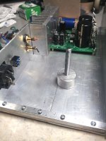
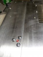
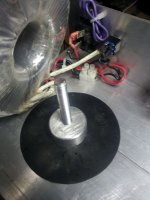
Dont know if this helps, but I avoided the protruding bolt head problem by using threaded rod, round stock and thin-wide head screws. The 5/16" threads were cut continuously through the puck and bottom as though they were one piece. The three screws are ~ 3/4" long and end ~ 1/32" short of the top of the puck.Exactly!
Another practical, basic question. Mounting a transformer via a bolt through the bottom of the chassis is rather unsightly. I would prefer not to have the bolt head protuding through the chassis. This seems to be managed often enough (the Bryston BDP-1 is one example that springs to mind).
Before I get out the J B Weld to the bolt head, how is this typically accomplished?
")
BTW: We often used Devcon - industrial version of JB Weld - to repair holes and cracks in major high pressure turbines at power generation plants. The stuff is simply amazing, but I don't remember an application where "pull stress" was the major consideration. Mostly used as a filler.
Attachments
Last edited:
Thanks Bob.
I have another question, this time relating to where to position the mains input earth connection. I have read that ideally this would be as close as possible to the chassis grounding point of other components within the enclosure. My power supply is powering a PC motherboard. I believe these are grounded to the chassis via the risers (although I note that anodising seems to rarely be removed around these risers). Do you think that I need cable the earth connection to a lug near one of these risers (on the other side of the chassis) or is it unlikely to be an issue in such a low voltage/current situation? Is it sufficient to simply find a convenient spot in the rear panel near the IEC inlet?
I have another question, this time relating to where to position the mains input earth connection. I have read that ideally this would be as close as possible to the chassis grounding point of other components within the enclosure. My power supply is powering a PC motherboard. I believe these are grounded to the chassis via the risers (although I note that anodising seems to rarely be removed around these risers). Do you think that I need cable the earth connection to a lug near one of these risers (on the other side of the chassis) or is it unlikely to be an issue in such a low voltage/current situation? Is it sufficient to simply find a convenient spot in the rear panel near the IEC inlet?
The smps of a PC is inside a closed ventilated metal box.
The mains enters that box and is "earthed" by the manufacturer to that metal box.
If you mount that box inside another unpowered chassis then the "fixing" of that smps box to the extra chassis automatically gives you the required "earthing".
The whole chassis and the SMPS box are earthed by the manufacturer's internal "earth" connection.
Hi. Take a look at the first post in this thread. I am building a simple 12V linear power rail to power a PicoPSU plugged into the motherboard. No smps. The toroidal transformer, rectifier diodes and snubber (eventually) will replace an external brick SMPS which is currently supplying 18V to my caps and regulator. So it is me installing the IEC inlet, grounding the mains input and wiring the transformer etc.
that led me to believe you are talking about a standard computer power supply system.a PC motherboard. I believe these are grounded to the chassis via the risers............ Do you think that I need cable the earth connection to a lug near one of these risers
If you have a powered chassis then you need to earth it by connecting the PE wire to Chassis permanently using a shortish length of that PE wire. No joints, no other connection. Just the PE wire bolted, or welded (NOT soldered), to the Chassis adjacent to the incoming mains cable.
Thanks
OK so just where convenient (adjacent to the IEC inlet) is fine? I was reading the information on Rod Elliot's site when the suggestion was made to ensure all components were earthed at the same point in the enclosure else one risks ground loops. Sounds like I'm worried about this too much for this simple application.
When you say "PE wire" I assume you mean insulated wire such as yellow 'n green insulated wiring from power cable. (I've not heard the term "PE wire" before.)
Agreed Andrew, I was trying to find out if SGK was using the PC PS cover in his build. I have a stripped down bare unit that's for bench work, but if I ever tried to use it to power an amp I'd have to look real close at grounding for safety considerations.
BTW: I had to return the PicoPSU I bought cause their best couldn't support power up on the Asus micro motherboard I have. It's a great product concept but care must be taken to match the PS and MBD specs.
Safety ground is a more often used term here in the U.S. for Power/Earth.
BTW: I had to return the PicoPSU I bought cause their best couldn't support power up on the Asus micro motherboard I have. It's a great product concept but care must be taken to match the PS and MBD specs.
Safety ground is a more often used term here in the U.S. for Power/Earth.
Last edited:
Basically all I am doing is building a 12V rail to power the PicoPSU unit, my sound card clock (upgraded) and a little 5V rail which powers my SSD. The original PicoPSU was powered by a 12V brick. I replaced this with an 18V brick, a couple of input capacitors a 12V (super) regulator and an output capacitor. I'm now replacing the 18V brick with a transformer and diodes (and eventually a snubber for the transformer). Whether I extend this to a full try-rail ATX supply and ditch the PicoPSU completely is to be seen.
Cheers guys.
Cheers guys.
Fig4 od ESP's link is slightly confusing.Thanks
OK so just where convenient (adjacent to the IEC inlet) is fine? I was reading the information on Rod Elliot's site when the suggestion was made to ensure all components were earthed at the same point in the enclosure else one risks ground loops. Sounds like I'm worried about this too much for this simple application.
When you say "PE wire" I assume you mean insulated wire such as yellow 'n green insulated wiring from power cable. (I've not heard the term "PE wire" before.)
The diagram shows the Safety Earth coming from the Disconnecting Network to the Chassis.
Technically this is wrong.
There must be no joins and no sharing of the PE to Chassis connection.
The green/yellow Protective Earth (PE) wire in the mains supply cable goes straight to Chassis.
Then later the Disconnecting Network goes to a different part of the Chassis. It DOES NOT share the same fixing as the permanent Safety Earth.
I use the UK PE short form and sometimes I refer to Safety Earth since this seems more internationally understood.
Another dumb question (please bare with me) relating to implementing a circuit schematic with practical point to point wiring.
Consider a CRC snubber, a capacitor across the secondaries followed by (or in parallel with) a capacitor and resistor in series across the secondaries. A schematic obviously shows the connection (wire) between one side of the first capacitor (cap1) and one side of the second capacitor (cap2) and the connection between the other side of cap1 and the resistor (r) attached to cap2.
When physically wiring these, do we need to have the two pieces of wire between cap1 and the cap2+r? Or can I simply solder everything in one place (two joins)? So one secondary meets one side of the pins of both cap1 and cap2 and the exit wire proceeds from there (one joint for 2 wires and 2 components) while the other secondary meets the other pin of cap1 and the pin of r and its exit wire proceeds from there (again one joint for 2 wires, 1 cap and 1 resistor)? (Obviously with the resistor and cap2 joined in series.)
If the latter above is true, then can we take this one step further and take the two "strings" (a) cap1 and (b) cap2 + r and solder them across the top of the rectifier diodes where the AC secondaries attach? (This may be a bit challenging to implement with 5mm pin pitch on cap1 I guess.)
Hopefully the above makes sense as a question... TIA
Nothing wrong with the questions, just that there will be many opinions...
When using any filter it pays to know what you are actually trying to achieve, and that means looking for real, with a wideband scope at what is there that shouldn't be. Without that information any filter can only be a generic and hopefully "catch all"
In practice a cap + resistor across each diode will stop most problems. Across the diode is the place to wire it so that lead/trace inductance doesn't reduce the effectiveness.
A C + R also across the secondary is good. Where you wire that depends on accessibility.
And having fitted all those again, a check for real with a scope is called for.
- Status
- This old topic is closed. If you want to reopen this topic, contact a moderator using the "Report Post" button.
- Home
- Amplifiers
- Power Supplies
- Help a novice steadily build a linear 12V power supply?