FWIW I tidied up the circuit in LTspice and refreshed the screen grabs above. New link here. My concern now is that if the simulation is even roughly right 15V secondaries don't provide enough voltage into the SPower HC regulator which has a 5V drop.
I must admit it looks marginal. 15*1.414 gives 21 volts dc. Less your rectifier losses... and this figure is important. So work upward (I'm going off your figures, I haven't checked the data sheets). So you need 17 minimum at the reg input. That figure has to include the dips in the ripple voltage voltage too. In other words its not just the average DC that must be 17 volts but the ripple voltage too must never drop below that figure. That leaves 4 volts to play with and its here you must minimise the rectifier losses which means looking for diodes or a bridge that has minimal volt drop at max current.
It's close. I was just looking at the diode data sheet again. (I don't have a Spice model for this exact diode as Cree hasn't provided one yet but I used a Cree Spice model for one of their older 600V diodes). Forward voltage for even 5A of current and temp of 175C is 1.5V. I have to account for 2 diodes, yes? So 3V of voltage drop. I'm hoping it's goldilocks.
Yes, two diode volt drops.
Why not use a conventional bridge, the losses are less. I can't understand the need for speed with 50/60Hz rectification Hi speed diodes are often quoted which we promptly damp with snubbers such that you have to send it a postcard if you want it to turn off quickly
I pulled this out of the bag, 1 voltmax loss per diode, heatsink mountable.
GSIB2540-E3/45 - VISHAY GENERAL SEMICONDUCTOR - BRIDGE RECTIFIER, 25A, 400V | CPC
Why not use a conventional bridge, the losses are less. I can't understand the need for speed with 50/60Hz rectification
Hi speed diodes are often quoted which we promptly damp with snubbers such that you have to send it a postcard if you want it to turn off quickly I pulled this out of the bag, 1 voltmax loss per diode, heatsink mountable.
GSIB2540-E3/45 - VISHAY GENERAL SEMICONDUCTOR - BRIDGE RECTIFIER, 25A, 400V | CPC
I keep mulling over the fuse/circuit breaker question. Good magnetic hydraulic circuit breakers in 3A seem hard to get. 2A are readily available but will they handle the initial rush? It seems they normally take a couple of seconds to trip by which point the current over the primary has settled down completely. Ostensibly 2A would be plenty if one can ignore those first couple of cycles.
... while I read {the Quasimodo} paper and wait for parts and access to an oscilloscope, how might I simulate the ringing in LTspice? Set K slightly less than 1 but how to observe the plots you posted in the Quasimodo thread?
If what you want to simulate is (the Quasimodo test-jig connected to a transformer), a simulation which will produce ten volts of ringing, I suggest you start with Figure 4 of the Quasimodo design note. You can simplify the circuit for simulation purposes: delete the entire LMC555 and MC1407 section at left, and replace by a single voltage source. Connect this source to M1's gate, and tell the source to produce fast-risetime (<20nsec) square waves, using the "PULSE" feature of voltage sources.
On the other hand, if what you want to simulate is (a power supply connected to the AC mains, but no Quasimodo in the circuit or even in the same room), then you might start with Hagerman's Figures 7, 8, and 9. Don't let his schematic confuse you, he merely drew the load in the center of the schematic. You might find it easier to understand if you redraw his schematic and put the four parallel branches in a different order. Placed at far left: Ct. Right of that, Cx. Right of that, Cs+Rs. Rightmost of all, the diode group. Hagerman's Figures 8-9 show that when he simulated this circuit, it barely achieved one volt PP of oscillatory ringing, and it was hidden rather well inside his 35VPP sinewave.
Whichever circuit you decide to simulate, you still face The Inescapable Gluteal Pain Of Snubber Design: what are the numerical values of your transformer's secondary leakage inductance and secondary capacitance? You gotta put these in your SPICE simulation, but they don't appear on transformer datasheets. They are quite difficult to measure in the lab; read Morgan Jones's article about snubbers in Linear Audio volume 5. He recommends that measure your transformer using a Hameg 8118 LCR Bridge that costs $2,300.00, and then extract the transformer parameters from the shape of the impedance-versus-frequency graph. Ugh.
This is precisely why Quasimodo the bellringer was invented: It lets you optimally snub a transformer without ever measuring that transformer's secondary inductance or secondary capacitance. Optimizing a snubber only takes 3 minutes, and you never touch a calculator, or a sinewave generator, or an LCR Bridge.
Thanks. My question related, I believe, to your points in the second paragraph above: how to observe transformer ringing, not the actual ringing of my particular transformer (which as you say is complex to simulate) but rather a simulation of any ringing. Where to look and how to look. I'll take a more detailed read through the paper.
If only I had a Quasimodo. I'm sure this isn't the only time one will come in handy but as someone starting out it seems like I need to collect a massive pile of stuff just to complete the first task I've set myself. ;-) Oh well, onwards.
(I will keep an eye out to see if there's another group buy etc.)
ok I now see that if I set the K1 statement for the transformer to less than 1 and really zoom in on the secondary voltage waveform I can observe ringing. I could observe the actual ringing of my transformer with an oscilloscope across the secondary (measuring anything to do with AC gives me the heebies) but then I'd still have to go through the math to derive the resistor and capacitor values.
Sorry for being slow.
Sorry for being slow.
ok I now see that if I set the K1 statement for the transformer to less than 1 and really zoom in on the secondary voltage waveform I can observe ringing. I could observe the actual ringing of my transformer with an oscilloscope across the secondary (measuring anything to do with AC gives me the heebies) but then I'd still have to go through the math to derive the resistor and capacitor values.
Sorry for being slow.
When you look at a real transformer on a scope you might be surprised what you see. Not just ringing effects but mains signalling devices, noise that looks for all the world like it might be "audio"... all sorts of things... and its really really hard to remove. Each case and transformer is different as well as the mains quality at any given location.
This is one reason why I include a certified EMI filter as close as possible to the mains inlet (EXAMPLE)When you look at a real transformer on a scope you might be surprised what you see. Not just ringing effects but mains signalling devices, noise that looks for all the world like it might be "audio"... all sorts of things... and its really really hard to remove. Each case and transformer is different as well as the mains quality at any given location.
Attachments
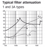
This is one reason why I include a certified EMI filter as close as possible to the mains inlet (EXAMPLE)
I've a similar set up on my amp but done discrete on a small PCB. Worthwhile I think.
I run all my equipment off an Isotek GII Titan with a Polaris as an extension block for sub 10A items. Hopefully all that mains garbage gets blocked there.
I would certainly hope so at the price
Exactly!
Another practical, basic question. Mounting a transformer via a bolt through the bottom of the chassis is rather unsightly. I would prefer not to have the bolt head protuding through the chassis. This seems to be managed often enough (the Bryston BDP-1 is one example that springs to mind).
Before I get out the J B Weld to the bolt head, how is this typically accomplished?
A thick steel base plate could have the 6mm to 8mm bolt welded to it. There may be some distortion and discolouration on the "outside" but this can be minimised by a good welder and what remains is just cosmetic and you should be capable of making that invisible.
I'd guess that 2mm steel plate will survive this, but if I were doing the welding I would use 3mm plate.
I'd guess that 2mm steel plate will survive this, but if I were doing the welding I would use 3mm plate.
- Status
- This old topic is closed. If you want to reopen this topic, contact a moderator using the "Report Post" button.
- Home
- Amplifiers
- Power Supplies
- Help a novice steadily build a linear 12V power supply?