Hello,
I need a overvoltage protection in case of short circuit in IC LM338K. As I am not technical, just a hobbyst, any help will be welcome. It would be even better if it is presented some circuit that has already been tested.
The LM338K is being used in the standard format of the data sheet and the applied load is 3.4 A with 6.3 v DC. The input voltage is 10.5 DC. I saw some options circuits in this forum and on the internet, but I could not identify any simple and efficient circuit for protection in case of short circuit LM338K.
Any help is welcome.
Hi woody,
Thank you for quickly replay.
No, it is about overvoltage. In my power supply arrangement the control voltage is fed into a lm338k regulator. This controls the current and hence the output voltage. Typically, in this type of regulator, the input voltage may be well in excess of the output voltage. If the series regulator CI in the power supply fails in a mode where it becomes a short circuit, the pre-regulated smoothed voltage level will be applied to the circuit being powered. This could cause significant damage to my tubes (valve amp).
I would like to use a led to indicate a failure in both cases: the overvoltage protection circuit fail or an overvoltage on output.
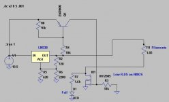
One possible idea might be to (a) sense overvoltage at the output, and if it is present, (b) short the input to ground with a very high current "crowbar", thus blowing the fuse and shutting down the entire circuit.
One possible implementation of a high current "crowbar" is the TYN616 Silicon Controlled Rectifier from ST Microelectronics (datasheet). It is reasonably priced, selling for (USD 1.14 @ DK) Notice its peak current rating: 190 amperes for 10 milliseconds. That is beefy enough to discharge filter capacitors as big as one hundred thousand microfarads. I doubt your filter capacitor is quite this big.
If, hypothetically, the voltage regulator fails with a dead short (0.1 milli-ohms) from input to output, the circuit shown below might possibly be one way to sense this fact and then trigger the SCR.
When the output voltage becomes "too high", Q1's base-emitter junction is forward biased, and so Q1 turns on. This pulls down the base of Q2, and so Q2 turns on. This sources current into the Gate terminal of the SCR and so the SCR is "triggered". The SCR becomes a perfect short, which blows the fuse and turns everything off. Then the user notices that her equipment has stopped working, so she sends it to the repair shop. They replace the shorted voltage regulator and the blown fuse.
Will I complete this circuit design for you? Will I construct a prototype of this circuit and test it for you? Will I give you an unconditional guarantee that this circuit will always work perfectly, no matter who builds it? I haven't completely decided yet.

Note to moderators: I tried to "attach" the image to this post, so that it will stay here forever, even after the free image hosting service wipes it off their servers. But I got a "file upload failed" error message, several times.
Edit: you could perhaps reduce parts-count a little bit, by substituting a voltage comparator IC (don't use an opamp!) instead of this discrete transistor overvoltage sensor. Just be sure that your circuit behaves properly when the input voltage ramps up (@ start-up), and it also behaves properly when the input voltage ramps down (@ shut-off).
One possible implementation of a high current "crowbar" is the TYN616 Silicon Controlled Rectifier from ST Microelectronics (datasheet). It is reasonably priced, selling for (USD 1.14 @ DK) Notice its peak current rating: 190 amperes for 10 milliseconds. That is beefy enough to discharge filter capacitors as big as one hundred thousand microfarads. I doubt your filter capacitor is quite this big.
If, hypothetically, the voltage regulator fails with a dead short (0.1 milli-ohms) from input to output, the circuit shown below might possibly be one way to sense this fact and then trigger the SCR.
When the output voltage becomes "too high", Q1's base-emitter junction is forward biased, and so Q1 turns on. This pulls down the base of Q2, and so Q2 turns on. This sources current into the Gate terminal of the SCR and so the SCR is "triggered". The SCR becomes a perfect short, which blows the fuse and turns everything off. Then the user notices that her equipment has stopped working, so she sends it to the repair shop. They replace the shorted voltage regulator and the blown fuse.
Will I complete this circuit design for you? Will I construct a prototype of this circuit and test it for you? Will I give you an unconditional guarantee that this circuit will always work perfectly, no matter who builds it? I haven't completely decided yet.
Note to moderators: I tried to "attach" the image to this post, so that it will stay here forever, even after the free image hosting service wipes it off their servers. But I got a "file upload failed" error message, several times.
Edit: you could perhaps reduce parts-count a little bit, by substituting a voltage comparator IC (don't use an opamp!) instead of this discrete transistor overvoltage sensor. Just be sure that your circuit behaves properly when the input voltage ramps up (@ start-up), and it also behaves properly when the input voltage ramps down (@ shut-off).
Last edited:
Hi AndrewT
Yes, it´s about an over voltage protection. For example, any volts over 7v DC will cut down the positive terminal and turn on a led. Maybe temperature sensor/switch to power OFF when the 338 gets too hot is more complicated, for example, that a crowbar protection circuit.
Yes, it´s about an over voltage protection. For example, any volts over 7v DC will cut down the positive terminal and turn on a led. Maybe temperature sensor/switch to power OFF when the 338 gets too hot is more complicated, for example, that a crowbar protection circuit.
Last edited:


One possible idea might be to (a) sense overvoltage at the output, and if it is present, (b) short the input to ground with a very high current "crowbar", thus blowing the fuse and shutting down the entire circuit. ...
THANK YOU!!! That exactly what I need. I will give it a try and see what happens.
You could also use ...
Hi RJM1
Sorry for the delay in give you a answer, but I've been busy these days.
This friday will be a holiday here in my country and I will try both circuits if the components I ordered from mouser arrive. After I finish the tests, I will post the results here.
Thank you.
- Status
- This old topic is closed. If you want to reopen this topic, contact a moderator using the "Report Post" button.
- Home
- Amplifiers
- Power Supplies
- Need help with overvoltage circuit - LM338k