If "CSS" means "Constant Current Source" then the minimum required voltage drop from input to output is the LM350's dropout voltage, plus the voltage dropped across the current sensing resistor (1.25 volts).
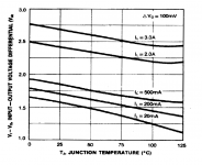
For example, using the figure from the Fairchild data sheet, if the load current is 2 amps and the junction temperature is 75 Celsius, then the the minimum required voltage drop from input to output is (2.25 + 1.25) = 3.50 volts.
For example, using the figure from the Fairchild data sheet, if the load current is 2 amps and the junction temperature is 75 Celsius, then the the minimum required voltage drop from input to output is (2.25 + 1.25) = 3.50 volts.
Attachments
Ok. Thanks a bunch!
Its a close call for me, but now I found some LM1085 in a drawer. They look like they have much lower dropout. I dont know how much to trust datasheets.
http://www.ti.com/lit/ds/symlink/lm1085.pdf
I cant find any calculator for this, and no examples for current regulation in the sheets either. Is the setup the same as for LM350 etc? Anybody have some calculation examples. I'm looking to regulate about 600 mA to set voltage to around 12 V from 14,3 V in.
Is the filament 12V or 12.6V?
12,6 but they run good on 12.0
If the adjust pin current is 100uA (like the 317 types) and you use a 121R from output to adj pin then the adj pin to ground should be 1030R for 12V.
With a 120R you need 1022R
Or use a 910R and a 200R pot for adjustment for the adj to gnd path.
Most of these adjustable types need a minimum current load...usually 10mA...hence the ~120R from the output to the adj pin.
")
With a 120R you need 1022R
Or use a 910R and a 200R pot for adjustment for the adj to gnd path.
Most of these adjustable types need a minimum current load...usually 10mA...hence the ~120R from the output to the adj pin.
I dont know how much to trust datasheets.
What do you mean? If a parameter is listed in the min or max column of the spec table, it is measured during production. If it's listed in the "typical" column, it's generally the average value of some rather large sample size of components. "Typical" values may or may not be measured in production. Min/max values are guaranteed either by design or by test. Most commonly by test.
The graphs are another story. They are typically developed from lab characterization of a handful of parts (in some cases more) and show typical performance.
At least that's the case with the big semiconductor houses (TI/National/Burr-Brown, Analog Devices, Linear Tech, ON, Micrel, etc.).
~Tom
Thanks guys. Maybe some misunderstanding here. I am going to regulate the voltage on the filaments by limiting its CURRENT. Ie no voltage regulator with resistor to ground.
On specs. The can often fool you. For example putting a reg devise close to its dropout limits might make it regulate but PSSR will be close to none. An LM350 needs according to measures up to 4 V for good PSSR.
What I was wondering was 2 things:
1. Does the curves on Dropout voltage apply also for current limiting configurations?
2. Can I use LM317/350 calculators also for LM1085 for example, regarding settings resistors?
It seems like the site has some problem with pictures etc now but fig 25 page 8 on this:
http://www.onsemi.com/pub_link/Collateral/LM350-D.PDF
The drop out voltage is from IN to OUT.
The CCS connected 317 has the ADJ Pin directly connected to the load.
The OUT Pin is connected via the dropping resistor to the Load.
The ADJ Pin sits @ ~1.25V below the OUT Pin.
You have already lost 1.25Volts of difference between IN and OUT.
At high currents and/or high ripple you will need quite a bit more.
You do this by increasing the IN voltage above the OUT voltage by the required drop out PLUS the ripple voltage.
The voltage at the load is ~ Dropout+1.25V+margin for voltage changes below the INPUT voltage.
- Status
- This old topic is closed. If you want to reopen this topic, contact a moderator using the "Report Post" button.
- Home
- Amplifiers
- Power Supplies
- Dropout voltage LM350