I just picked up a Sure Electronics TAS5630 board to cobble together an inexpensive instrument amp. I've got a giant power transformer from a failed Sansui AU-D7 that puts out about +/- 57v with a low load/idle. The schematic suggests the transformer is 41v-0-41v.
This amp will likely take a beating, so I'm looking to have a PS that can handle about 50v 12A. Unfortunately I can't do a simple CRC design where the board idles at about 100mA which is probably way less than the AU-D7, and I can't exceed 52v.
So I likely need a voltage regulator of some sort. I've searched. I've googled, but I've not had success finding anything that can handle 50v 12A. Any suggestions? It doesn't need to be quiet or super accurate.
I suppose I can just scrub off some power with some big resistors, but that's not very nice.
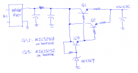
How about something simple that isn't quite a "regulator"? What if you just build an enormously beefy, oversized emitter follower or source follower, put a fixed reference voltage on its base/gate, and accepted the voltage on its emitter/source as "good enough"? There's no feedback control system; you don't sample the output, compare to a reference, and use the difference ("error voltage") to adjust the regulator.
Here's the outline of the idea; details such as fusing, Emitter-Base reverse bias protection, start-up inrush current limiting, load disconnects, and protection when the other rail fuse blows, are omitted. But perhaps they are crucial.
Here's the outline of the idea; details such as fusing, Emitter-Base reverse bias protection, start-up inrush current limiting, load disconnects, and protection when the other rail fuse blows, are omitted. But perhaps they are crucial.
Attachments
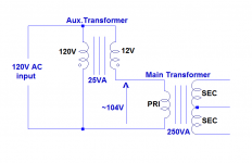
A simple and effective solution is to use a small transformer connected as an autotransformer in front of your transformer: for example, a 120V to 12V transformer will shave off a little more than 10% of the voltage and only needs to have 10% of the VA rating of the main transformer
@elvee: Not sure I understand. So put the primaries of the autotransformer in line with one of the primaries of the main transformer?
I could reconfigure the iron for 220v on the primary side. That would about halve the output on the secondaries, but I may have trouble getting anywhere close to 50v.
I could reconfigure the iron for 220v on the primary side. That would about halve the output on the secondaries, but I may have trouble getting anywhere close to 50v.
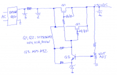
If you do want a feedback control system including a potentiometer that lets you fine-tune the output voltage, perhaps a few parallel Nchannel MOSFETs and an NFB loop would be a possibility. I've shown 2 parallel devices but since they are so inexpensive ($1.56 qty 1 @ DK), you might prefer to build yourself an enormous SOA by connecting 4 or 6 of them in parallel.
Again, many crucial real-world details are omitted from this conceptual sketch.
Again, many crucial real-world details are omitted from this conceptual sketch.
Attachments
No, here is what I mean. You keep the input of your main transformer configured for 120V, but you subtract the voltage from the auxiliary transformer.@elvee: Not sure I understand. So put the primaries of the autotransformer in line with one of the primaries of the main transformer?
The drop will be more than 12V, because the regulation of the aux transformer will work backwards
Attachments
Have a look at the PSU im building http://www.diyaudio.com/forums/power-supplies/244796-new-psu-power-amp-2.html#post3682060.
i ve made a few changed since my last upload but will upload the final version tonight.
Cheers
Dom
i ve made a few changed since my last upload but will upload the final version tonight.
Cheers
Dom
Thanks everyone for your posts. I have a mountain of transformers so that's a real option.
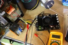
I haven't gotten any big ps capacitors yet, so I'm going to use what I've got for now in a CRCRC config for initial testing. I think big 2 ohm resistors for the R if I can find them. And then a bunch of parallel 47uF 63v LOL for the first C, and then massive 600uF 500v film capacitors for the other two C's. Just for testing.")
I haven't gotten any big ps capacitors yet, so I'm going to use what I've got for now in a CRCRC config for initial testing. I think big 2 ohm resistors for the R if I can find them. And then a bunch of parallel 47uF 63v LOL for the first C, and then massive 600uF 500v film capacitors for the other two C's. Just for testing.
So at this point it has a full wave center tap ground rectifier with 564uF (12 x 47uF 63v) followed by a 2 ohm 10w wire wound resistor. Not pretty, but it works. With the amp powered up and a light load voltage is solid at 50.9. I'd expect this to sag a bit under heavy use, but not much.
In the photo you can see the smaller transformer used to drop the voltage.
In the photo you can see the smaller transformer used to drop the voltage.
Attachments
How beautifully clever and simple - first time I have seen that solution.
A primary side buck circuit. Not uncommon. Also the same thing concept can be used to boost the primary voltage say if there is a long transmission of wire supplying the power and sustains voltage loss in the wire. Something like a pump motor would not be happy running at low voltage and would fail.
Yes I understood that - just depends on the phase of the auto-transformer secondary.
The more I think about it I seem to remember this was covered in Transformers 101 many many years ago. I'm a little disappointed with myself. But then again, in those days, if it didn't look like a motor cycle or a girl....
The more I think about it I seem to remember this was covered in Transformers 101 many many years ago. I'm a little disappointed with myself. But then again, in those days, if it didn't look like a motor cycle or a girl....
- Status
- This old topic is closed. If you want to reopen this topic, contact a moderator using the "Report Post" button.
- Home
- Amplifiers
- Power Supplies
- Help with PS design