") .
.Hello!
This is my first post on the forum, so I have to thank you all for sharing your knowledge and helping others with so much patience (which I will try not to abuse).
I want to build an F5 stereo amp and a power supply to power it.
Due to some placement constraints I would like to build it as 2 smaller boxes: one with the power supply and another with the amplifier PCBs that can be stacked one above the other.
If I do this in 2 chassis is it ok to connect the 2 chassis with GX20 connectors with 4 pins: V+, V-, Main Audio Ground, Chassis Ground?
I draw a simplified version of the PCB that (I think) would be suitable for the F5 and other FirstWatt designs.
I hope someone will find it useful as well. (CircuitMaker also renders a nice 3d picture of the populated PCB, so it can be useful to look for certain details in a PCB).
CircuitMaker project
Good morning,
the PI parallel resistor in the Universal PSU are 0.47 Ohm 3W. I need to replace them with 1 resistor (of course 1 for + and 1 for -). The calculation would be to replace them with 0.12 Ohm 25W. I don't find it. Can I replace them with 0.10 Ohm 25W ? Thank you in advance.
the PI parallel resistor in the Universal PSU are 0.47 Ohm 3W. I need to replace them with 1 resistor (of course 1 for + and 1 for -). The calculation would be to replace them with 0.12 Ohm 25W. I don't find it. Can I replace them with 0.10 Ohm 25W ? Thank you in advance.
Soldered power supply PCB for my up and coming F6 build.
I soldered in the capacitors in but had a thought afterwards.
I put 2x 22000uf caps on the input side and 15000uf on the output side. (Had 4 of each on hand) What didn’t occur to me until afterwards is does it matter if i do this? Should it be 22000 on the output side instead? Is it ok unbalanced like this or am I just over thinking this.
Thanks
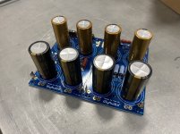
Image for reference:
No problem with the cap configuration, looks all fine.
2 things that you need to watch out
1) You haven’t connected the ground points in the pcb: it is tagged on the pcb board, you can also check 6l6’s build guides for a picture
2) Your transformers secondaries: those caps are rated 25v, you should be fine with normal 2x18 v secondaries which will give 23-24v rails: but you should not go above that value
Hope it helps
Thanks Syracuze.
Yeah I do know about the jumper. Have not decided if I will separate the PCB yet so will leave it til last. Also haven’t installed LEDs yet.
Yep at the limit at 25v caps but I think it will be fine as long as I stay under 25v.
Living on the edge. Lol.
Had them in stock so didn’t want to waste em....
I’ll double check output of rectifier before powering up the boards.
Cheers
I put 2x 22000uf caps on the input side and 15000uf on the output side. (Had 4 of each on hand)
Totally fine.
As noted by others, attach the grounds, and remove the output snubber. (R11 R12 C17 C18)
Does anyone know when these might be coming back in stock?
Thank you to whoever put those back in stock long enough for me to order one (they appear to be out already)! Time to order some parts to populate it now...
-Geoff
Nobody knows. That’s the problem. In theory it’s supposed to damp ringing in the PSU from uneven loads but a class A amp has an almost constant draw, so nothing will ring...
If there’s ever a revision to this PCB, it’s the first set of pads that are going to be removed.
If there’s ever a revision to this PCB, it’s the first set of pads that are going to be removed.
I agree with the esteemed 6L6 completely. I would add: please remember that the design goal of this PCB is embedded right there in its very name
Universal Power Supply – diyAudio Store
See it there, the word Universal. Want to use TO-220 diodes with 2 legs? Sure this PCB accommodates those. Want to use TO-220 diodes with 3 legs? Sure it accommodates those too. Want to build a CRC supply with 5 parallel devices for the "R"? Sure it accommodates that. Want 7 parallel resistors instead? Sure, no problem. Want no R's at all? No problem.
Similarly: want to have input snubbers across your transformer secondaries? Sure, the PCB accommodates those. Want to have output snubbers across your final DC outputs? Sure, the PCB accommodates those too.
WHY are the output snubbers included? Because the original PCB designers thought it wouldn't be a universal PCB design without them.
Somebody, some day, might want them. Therefore, put them in! Make the customer happy.
Does member 6L6 want them? Evidently not; strong No. Do *I* want them? Another strong No. Do YOU want them? The only person who can answer that question is you.
6L6, thanks for the guide and others for the valuable information from the pages of the thread.
I'd like to use TO220 2 legged diodes (MUR820) which have a pinout of Pin1=K Pin3=A with the middle pin removed at the factory. I could bend these like 6L6 did in the guide to get the cathode pin to the center pad.
Could i also use them in the TO-247 pads? the spacing lines up pin1-center (cathode) pad and pin3-right (anode) pad without needing to bend leads.
Many thanks
- Home
- Amplifiers
- Power Supplies
- diyAudio Power Supply Circuit Board v3 illustrated build guide