You need to change the transformer.
His default is basically suitable for driving a valve amplifier.
Then it should settle much more quickly and the 10second delay should work. It might even work with a 2second delay.
It stabilizes almost instantly. the "swing" or difference is less significant now.
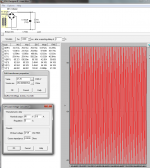
rC = 2.405 VS rCRC= 2.379 .
Note: It is approx 2.5 V however.
Ignore that, the values changed from 20mF to 20uF
Attachments
Last edited:
You need to change the transformer.
Do you mean the transformer settings (Ex: winding R, voltage, etc?) or is there a way to actually change the transformer to a different type (ex:toroidal)
If the former; than I get 0.7V ripple down to 0.02V by going from rC to rCRC
Attachments
Last edited:
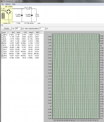
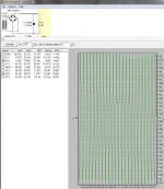
The voltage is higher in the rC compared to the rCRC (which makes sense). Although I expected it to be much higher for both.
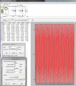
If I look at the same simulations without the reporting delay (ex: 0), I can see the sharp saw tooth peaks begin to round out via the change from rC to rCRC. Both systems stabilize within the first second or less.
NOTE: with 0 sec reporting delay, and with "softstart" selected "OFF", it warns that that the maximum 99A was exceeded @ .184 sec. This is fixed by using softstart... Although the graphs don't show any exceeding parameters.
Attachments
Last edited:
Note:
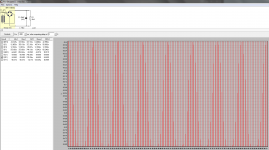
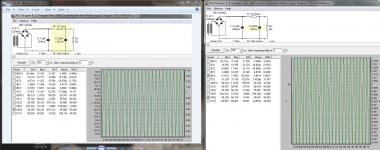
Ic1rms and Ic2rms.
The ripple capacity of the first capacitor needs to be much higher for an rCRC filter.
Maximum power in R1 is ~6.3W if you can sustain that current continuously. The duty factor is ~50%. But max power is only delivered during dummy load testing, not during music/audio reproduction.
Ripple rC = 1.38Vpp and for rCRC 0.56Vpp That's a 7.8dB reduction in mains ripple.
But you have reduced the capacitance directly attached to the amplifier from 40mF to 20mF. The amp sees a higher source impedance for the rCRC and thus does not quite perform as well for locally generated rail ripple.
You could try pricing a pair of 4700uF, or 5off 2200uF, instead of a singleton 20mF. See how they compare for ripple capacity and for ripple reduction.
Note:
Ic1rms and Ic2rms.
The ripple capacity of the first capacitor needs to be much higher for an rCRC filter.
Maximum power in R1 is ~6.3W if you can sustain that current continuously. The duty factor is ~50%. But max power is only delivered during dummy load testing, not during music/audio reproduction.
Ripple rC = 1.38Vpp and for rCRC 0.56Vpp That's a 7.8dB reduction in mains ripple.
But you have reduced the capacitance directly attached to the amplifier from 40mF to 20mF. The amp sees a higher source impedance for the rCRC and thus does not quite perform as well for locally generated rail ripple.
You could try pricing a pair of 4700uF, or 5off 2200uF, instead of a singleton 20mF. See how they compare for ripple capacity and for ripple reduction.
Thank for the info! The reason I was sticking with 40,000uF per rail was because of OS's recommendation in the build guide. He may have been using an rC though, he referenced an earlier PSU (V2).
I wish I had the proper background to make these kinds of decisions better! I'm slowly trucking along though, so any progress is good progress now
")
Note:
You could try pricing a pair of 4700uF, or 5off 2200uF, instead of a singleton 20mF. See how they compare for ripple capacity and for ripple reduction.
do you mean to keep the C1 @ 20kuF, and parallel a pair of 4700uF or 5(2200uF) or C2?
I've been playing with R1 as well, and in order to reach the target Voltages, it apperas that less R = better results (closer to 65V; which makes sense)
EDIT: I guess I would have to combine C2 and C3 into C2 if this is the case. PSUD2 doesn't allow for separate C filter sections after the initial one.
Since the last C is what the amplifier/Load sees directly and any previous C is isolated from the load by the R, then reducing the last C reduces the performance of the amplifier.
So any experimentation in the simulator is with respect to altering C1 to see if money or space could be saved without significant reduction in performance.
So I suggested 40mF for last C to match the rC version and suggest reducing first C to half value, i.e. 20mF. Try that.
Then try 10mF for C1 and 20mF for C2 and see what you lose compared to 20mF and 40mF for the rC versions.
Finally to get a high ripple capacity it is generally much cheaper to use multiple small caps for C1 rather than a big expensive high ripple capacity singleton.
That's where the 2*4700uF (=9400uF), or 5off 2200uF (=11mF) came into the equation/simulation.
Since the maths is pretty complicated, the sim is capable of showing many details that are difficult to calculate and also shows more than I could measure since I don't have the equipment.
Since the last C is what the amplifier/Load sees directly and any previous C is isolated from the load by the R, then reducing the last C reduces the performance of the amplifier.
So, I guess its fair to say: It's best to leave this at 20kuF per rail per the BOM.
So any experimentation in the simulator is with respect to altering C1 to see if money or space could be saved without significant reduction in performance.
I believe it would also be fair to say that the results are similar to each other in the examples of C1=9400uF, C2=20kuF VS. c1=10kuF, C2=20kuF (which I would expect given the very close numbers). The difference being cost (I haven't confirmed this yet).
Finally to get a high ripple capacity it is generally much cheaper to use multiple small caps for C1 rather than a big expensive high ripple capacity singleton.
That's where the 2*4700uF (=9400uF), or 5off 2200uF (=11mF) came into the equation/simulation.
Since the maths is pretty complicated, the sim is capable of showing many details that are difficult to calculate and also shows more than I could measure since I don't have the equipment.
I believe this confirms my thoughts above.
1) Given the experiments I/We have done, I would assume that a lower value of R1 (0R1 is the lowest the sim would allow), achieved by combining the recommended(for the PSU V3) 4-5 x 0R47 3W in parallel would achieve the optimal number (aside from just jumping the cap banks together). Does that sound like a fair statement?
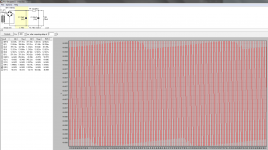
If the above is all true, the simulated rail voltages would be approx +/- 56V which is approx 7-10 V lower than originally expected
Attachments
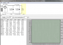
20kuF/ 0R1175/ 20kuF appears to alter the ripple to the load from 1.1V to 0.66V when compared to 10kuF/ 0R1175/ 20kuF. It doesn't appear to have a big effect on C1 / C2. although the load across R1 seems a bit high.
This stuff is a bit advanced for my current level of understanding I think.
This stuff is a bit advanced for my current level of understanding I think.
The lower rail voltage won't be bad. Just compare a few of the caps that fit the board at about the value you want for the first c in the crc filter and choose one with a relatively high ripple rating. Use the soft start and you will be fine.
I can't seem to remember if you've built a Honey Badger. If so, what did you use for the PSU?
I thought I had the PSU figured out with 8X 10kuF per the BOM, and while trying to calculate what to do with the resistors, AndrewT opened up a whole world of options for the Caps
. The joys of DIY! The good news is that I'm learning a lot, even if it doesn't seem like it sometimes
.While I'm here in the PSU section, I've been looking at a couple of these little guys
GBPC3502 Fairchild Semiconductor | Mouser for the Rectifier Bridges. Can anyone see a reason why I shouldn't use them?
GBPC3502 Fairchild Semiconductor | Mouser for the Rectifier Bridges. Can anyone see a reason why I shouldn't use them?
I have not built a badger but I have built some of Ostripper's other designs that are similar. I have also used the stores power supply boards. His designs seem to be tolerant of parts selection and voltages within reason. I say follow the BOM and get a basic unit working. Take comfort in the many builds done this way that work great. The chassis and wiring of the amp and power supply are in my opinion the most difficult tasks for those of us building proven designs that others have worked out.
The linked bridge rectifiers look good.
The linked bridge rectifiers look good.
I have not built a badger but I have built some of Ostripper's other designs that are similar. I have also used the stores power supply boards. His designs seem to be tolerant of parts selection and voltages within reason. I say follow the BOM and get a basic unit working. Take comfort in the many builds done this way that work great. The chassis and wiring of the amp and power supply are in my opinion the most difficult tasks for those of us building proven designs that others have worked out.
I tend to make things harder than they need to be. It's in my nature, lol
Thanks!The linked bridge rectifiers look good.
I can't wait to start building this when I come home next rotation. It usually takes 2 weeks for shipping to NL, so my parts should show up while I'm away.
You are looking at volts and currents and ripple while the load is pulling 7A continuously...............If the above is all true, the simulated rail voltages would be approx +/- 56V which is approx 7-10 V lower than originally expected
Try reducing the load to 1A and/or 500mA to see what it looks like when the amplifier is ticking along producing audio @ -20dB relative to maximum.
You are looking at volts and currents and ripple while the load is pulling 7A continuously.
Good Point, I was stuck on "worst case" thinking. Kind of missed the big picture.
Try reducing the load to 1A and/or 500mA to see what it looks like when the amplifier is ticking along producing audio @ -20dB relative to maximum.
I assume this would be as simple as increasing the speaker load(R) until I get a draw of 500mA to 1A? I will play around with some examples in PSUD2 later(when I have PC access again).
I really like being able to see the chages in PSUD2, and how they affect the various components (Ex: increasing V @ C1, etc.). One of these days I'll try to figure out spice as well
.You are looking at volts and currents and ripple while the load is pulling 7A continuously.
Try reducing the load to 1A and/or 500mA to see what it looks like when the amplifier is ticking along producing audio @ -20dB relative to maximum.
I had a quick play in PSUD (wife commandeered the PC today
), and 4700uF X 4 + 20kuF = very similar to 20kuF + 20kuF . R1=0R1175 (4 X 0R47, 3W), and "sees" approx 1/4 W.These findings were observed at an R2(load) = 127R, which draws 0A5. I will model an R2=8R and compare "worst case" later. I'll post all 4 screenshots tonight for anyone mildly interested
.4700uF X 4 + 20kuF = very similar to 20kuF + 20kuF .
Should read 9400uF (4700uF X 2) + 20kuF (10kuF X 2) per rail.
Snubbers for F6? 22K Bleeders??
Hi,
I'm building an F6 amp and using the diy power supply. The F6 schematic does not call for input or output snubbers. Should I use either? I have the resistors and caps on hand. I *think* I recall reading that Class A doesn't need output, but input snubbers won't hurt.
If I omit either of the snubbers, I assume I should wire the PCB where the snubbers should be. Is this assumption correct?
Finally, I'm a little confused on the bleeder resistor. The schematic calls for 2K2 but I purchased 22K- on the high end of the BOM. Will the 22Ks work?
- Home
- Amplifiers
- Power Supplies
- diyAudio Power Supply Circuit Board v3 illustrated build guide