I'm building a high voltage push-pull SMPS (300-400v) and need help understanding the current limiting of the SG3524
I was going to shunt the mosfets source's to ground and measure the drop across that "resistor" (12~10ga solid wire).
Please take a look at this datasheet as it's the one I'm using. http://www.ti.com/lit/ds/symlink/sg3524.pdf
In the datasheet on page 9 figure 7 it shows pin 4 to ground and pin 5 as input. On page 13 figure 15 it shows pin 5 to ground and pin 4 as input.
I'm guessing the page 11 drawing of "foldback limiting" is measuring a flyback current? which is reversed? This is where I'm confused.
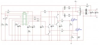
fig.7 seems to be a buck regulator case, current is measured when transistors are off, current continues to flow thru inductor, load, Rs, diode back into inductor ... thus "ground" side of Rs is actually more positive than other side, hence Lim+ at "ground".
in fig 12 emitter current of switcher transistors is measured when transistors are on, current flows thru RS to ground, so ground side is more negative than other side, hence Lim- at ground.
think you got it right ...
in fig 12 emitter current of switcher transistors is measured when transistors are on, current flows thru RS to ground, so ground side is more negative than other side, hence Lim- at ground.
think you got it right ...
So many questions...
I need a ~150w power supply to output a regulated ~350vdc with a current limit of around ~430ma. Above 430ma the voltage could/should sag as a means of protection. I'm still deciding on what IC to use.
1: Current mode? Voltage mode? Can someone explain the difference? 3524, 3535, 3825, 494, ect?
2: Will a pair of IRFz44 handle 150w?
3: Is the totem pole needed with a single pair of mosfets?
4: Am I on the right path with the above schematic?
5: Should I be measuring the secondary current instead?
6: Would you like to learn to fly?
7: Would you like to see me try?
I'm sure it's been said a million times but once the design is final, I'd like to order some extra boards or even make kits to sell.
I'm still looking for help.
I drew this up for the 3525 but without current limiting and remote turn-on was added. I eliminated the gate drivers because I think the 3525 can handle 2 mosfets. I still have to work out some of the values.
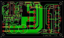
I started a pcb layout and had a friend cut one in vinyl for etching mask. It worked very well.
I drew this up for the 3525 but without current limiting and remote turn-on was added. I eliminated the gate drivers because I think the 3525 can handle 2 mosfets. I still have to work out some of the values.
I started a pcb layout and had a friend cut one in vinyl for etching mask. It worked very well.
Attachments
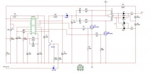
Here's my pcb layout so far. I've been trying to get it as small as I can. I forgot to add input filters though. I may have to just use an inline filter choke. Regulation goal is around ~350vdc.
Layout doesn't match the schematic 100%. I left a few pads for snubbers.
Layout doesn't match the schematic 100%. I left a few pads for snubbers.
Attachments
I built the circuit above and it works... without a load. 12vdc in gets me adjustable 200-380vdc out but as soon as I put a load on it (two 40w laps in series) the output drops off, input current climbs to 8A, and the mosfets get hot. The switching frequency may not be high enough?
Transformer is a 10t CT primary and a 160t CT secondary with four 1n4006 diodes for the rectifiers (all I had on hand). I'm pretty sure this core is an ETD34 but the bobbin didn't line up with my PCB which was drawn using a ETD34 pinout. I saved this core from an old PC power supply. I'll measure it in a moment to see if the core is the same as the ETD34.
Is there any tricks to getting transformers apart without breaking them? I broke 6 trying to get a good one.
I built the circuit above and it works... without a load. 12vdc in gets me adjustable 200-380vdc out but as soon as I put a load on it (two 40w laps in series) the output drops off, input current climbs to 8A, and the mosfets get hot. The switching frequency may not be high enough?
Transformer is a 10t CT primary and a 160t CT secondary with four 1n4006 diodes for the rectifiers (all I had on hand). I'm pretty sure this core is an ETD34 but the bobbin didn't line up with my PCB which was drawn using a ETD34 pinout. I saved this core from an old PC power supply. I'll measure it in a moment to see if the core is the same as the ETD34.
Is there any tricks to getting transformers apart without breaking them? I broke 6 trying to get a good one.
Hi,
are you sure 1N4006 are fast enough to manage your high switching frequency.
By the way I would use an octocoupler (4N35) on feedback for pwm just to isolate 12V power supply GND from audio GND.
IMHO, opltos and zener series could be the way to follow.
I built the circuit above and it works... without a load. 12vdc in gets me adjustable 200-380vdc out but as soon as I put a load on it (two 40w laps in series) the output drops off, input current climbs to 8A, and the mosfets get hot. The switching frequency may not be high enough?
Transformer is a 10t CT primary and a 160t CT secondary with four 1n4006 diodes for the rectifiers (all I had on hand). I'm pretty sure this core is an ETD34 but the bobbin didn't line up with my PCB which was drawn using a ETD34 pinout. I saved this core from an old PC power supply. I'll measure it in a moment to see if the core is the same as the ETD34.
Does not necessarily sound too bad...
Getting the 40W bulbs to glow might/will require more current than your supply can provide.
12*8 is only 96W, and that might be the maximum of your supply as it is configured now.
Change your output rectifier diodes. You are loosing output power in them.
Your core could be an ER-core, not an ETD... That does not matter as sush, but are you sure it does not have an air gap in it?
Computer power supplies "usually" are flyback topology. Using flyback core in a center tapped push-pull topology is not that good of an idea...
I would use an octocoupler (4N35) on feedback for pwm just to isolate 12V power supply GND from audio GND.
IMHO, opltos and zener series could be the way to follow.
What would be the reasoning for isolation? It's not line powered.
Does not necessarily sound too bad...
Getting the 40W bulbs to glow might/will require more current than your supply can provide.
12*8 is only 96W, and that might be the maximum of your supply as it is configured now.
Change your output rectifier diodes. You are loosing output power in them.
Your core could be an ER-core, not an ETD... That does not matter as sush, but are you sure it does not have an air gap in it?
Computer power supplies "usually" are flyback topology. Using flyback core in a center tapped push-pull topology is not that good of an idea...
The two 120v 40w bulbs are in series. If I adjust the voltage to 240v it should only draw 40w.
I held the cores together up to the light and didn't see any light shining through and the bobbin also floats on the core when holding the assembly together so it's not bottoming out on the bobbin either. I'm pretty sure it's not gapped. I am holding the halfs together with tape for now incase I have to change a winding. It does audibly sizzle when the PWM backs off but that's probably because the core is not very secure. Is that normal?
You are probably right about the diodes. They got really hot with not so much as a dim glow on the bulbs. Can you recommend a diode close in size to the 1n4006 that has higher speed? When I looked through Mouser I could only find larger TO220 diodes. My guess is I only need a 1A diode. 4 should do 100w output right?
Also, my secondary capacitors are only 10uf on each rail. I have more on the way but 10uf should be ok for testing shouldn't it?
Thanks for the input.

So it dawned on me to just remove the diodes and connect the bulbs right to the secondary windings. Now they light up bright. I'm seeing about 10A draw on the input. I'm not sure my meter can read AC at such a high frequency but it shows 200v. The heatsink gets slightly warm. I'm seeing ringing on the primary winding and also on the gate drive so I'll have to track that down. I have one .001uf 22ohm snubber across the primary but I'm not sure it's working because the resistor is cold. I may have to increase the capacitor value.
My layout would be easy to change to accept TO220 package diodes but I've had the trouble in the past of finding fast high-voltage dual diodes in a TO220 package.
Would these diodes work? http://pdf1.alldatasheet.com/datasheet-pdf/view/116346/SANKEN/FMU-22S.html
Or these? http://www.mouser.com/ds/2/149/FFPF60SA60DS-244013.pdf
I can wire them in any fashion that's required.
Last edited:
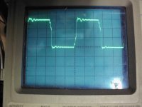
Your primary waveform is perfect...
You need ultrafast diodes,
recovery time in the nano second -range...
The ringing isn't an issue? Couldn't it cause RF interference? Anyway to dampen it or is it typically acceptable the way it is?
I've installed the new diodes and it works now but I have another problem.
I connected three 25w bulbs in series for a 75w load. I've adjusted the voltage output to 350v. At 10-12v input everything works great. The mosfets stay cool with minimal heatsinking. If I turn the input voltage up to 15v, the mosfets start to get hot quickly. Voltage still stable at 350v +/-1v.
Ideas?
- Status
- This old topic is closed. If you want to reopen this topic, contact a moderator using the "Report Post" button.
- Home
- Amplifiers
- Power Supplies
- SG3524 SMPS help needed.