I haven't seen any measured data which suggests that mounting a transformer to a chassis, has any effect upon the damping factor zeta.
Since zeta depends upon Rdamping, Ltotal, and Ctotal {equation (A.10) in QM design note}, it seems reasonable to assume that if zeta changes, the reason might be that one or more of R, L, and C have changed. But first, study the measured data.
Since zeta depends upon Rdamping, Ltotal, and Ctotal {equation (A.10) in QM design note}, it seems reasonable to assume that if zeta changes, the reason might be that one or more of R, L, and C have changed. But first, study the measured data.
Would it be just a matter of changing a capacitor to set QUASIMODO for 60 hz?
I know it is antithetical and beyond the pale but I have been working with half wave rectifiers on line amps and my phono amp and find there is something that is different in the background noise. Within brute force supplies (CLCLCLC) I have as much quiet as I did with all kinds of regulators including the JUNG DIDDEN reg but I was never sure if it was absolutely right since it seems to require a test bench to be sure it is operating correctly. and if I had one I would not know what to look for.
Just wanted to give a context. Inspired by the Marantz 7.
I would think snubbing a half wave would be just as important. Is this a simple mod to the QUASIMODO by any chance?
Let's attempt to answer this question by studying the way an unmodified, "stock" Quasimodo works.
Please connect your Quasimodo to a transformer secondary, short all other windings, and remove the trimmer Rs from its socket. Thus Rs=Infinity and you ought to get a LOT of ringing. Adjust the vertical setting, trigger setting, etc., to get a nice tall legible display. Adjust the horizontal sweep rate so you can see the stimulus and the first few cycles of ringing. (I'm guessing this may take 1 usec/div to 10 usec/div). Take a scope photo / screen_capture of the scope face display and post it here, calling it Fast_Picture. Be sure to write down the horizontal sweep rate (or circle it in the scope picture if displayed).
Now change the horizontal sweep rate on your scope and make it slow enough that you can see two stimulus pulses on the scope face. This will probably require a setting in the neighborhood of 2 milliseconds/division or so. Take a scope photo / screen_capture of the scope face and post it here, calling it Slow_Picture. Be sure to write down the horizontal sweep rate (or circle it in the scope picture if displayed).
Once we have Fast_Picture and Slow_Picture, publicly posted here for all to see, we can analyze the situation.
As always, Mr. Johnson I know I am a child in comparison to your electronics abilities. I hope that doesn't sound curt because I mean it sincerely.
I am glad to do as you asked. I got an oscilloscope just be able to use QUASIMODO, the RIGOL that is inexpensive and many people say is good.
But being tentatively pokey using the thing I will wait until Saturday so I will have enough time to get it right.
You must understand being the eternal dilettante that I have to admit I am, my real understanding of electronics is very limited and I have done nothing more than what I needed at the moment to further it. Forgive me for hoping for a simple capacitor value substitution!
I know I need to get more comfortable with the 'scope so I will look forward to doing this and post the picture.
Mark -- did you ever consider building the "EMI Sniffer" -- starts on page 54 of Linear Tech ap note 70. http://cds.linear.com/docs/en/application-note/an70.pdf
I bought one from Mr. Carsten himself! Dialled the phone number on the LT app note, he picked up, and we talked. I asked if he sold finished units and he said yes.
This was pre-Quasimodo, when I was searching for a way to measure rectifier-induced transformer ringing. Carsten's EMI sniffer turned out not to be what I wanted; it wouldn't give useful output when dialling the damping factor upwards towards zeta=1.0. And it required the transformer + rectifier + filter caps to be connected together & driving a heavy load. No problem for existing audio equipment, moderately painful for a brand new transformer straight out of the box.
A battery powered bellringer test jig + oscilloscope, gave me exactly what I wanted, and I found it to be very easy to use. So I retired the EMI sniffer probe.
(BTW I also bought some E-field and B-field probes from Vietnam after an enthusiastic review on EEVblog: (link to Youtube). Never did anything useful with them, however.)

(BTW I also bought some E-field and B-field probes from Vietnam after an enthusiastic review on EEVblog: (link to Youtube). Never did anything useful with them, however.)
My world is now mostly below 10MHz.
I built a sniffer from a hard drive head and coil on a wooden dowel. Encased in a brass tube (Michael's Stores) which had two small slots.
Has anyone ever measured the inductance of a fuse? Specifically, a slow-blow fuse such as "F1" in the schematic below, placed in series with the transformer secondary. The inductance of F1 directly adds to the self-inductance of the secondary.
Conventional wisdom (D. Self et al) suggests that F1's job is to protect the transformer in case the bridge rectifier fails as a short. While F2's job is to protect the power supply in case the output transistors fail as a short. The transistors are destroyed of course; F2 is simply trying to prevent further damage inside the PSU.
Thanks for any measured data or laboratory results!
_
Attachments
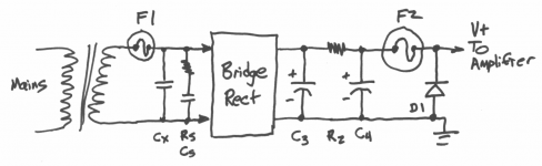
F1 and F2 are both unnecessary, if one fits a close rated fuse to the primary.Has anyone ever measured the inductance of a fuse? Specifically, a slow-blow fuse such as "F1" in the schematic below, placed in series with the transformer secondary. The inductance of F1 directly adds to the self-inductance of the secondary.
Conventional wisdom (D. Self et al) suggests that F1's job is to protect the transformer in case the bridge rectifier fails as a short. While F2's job is to protect the power supply in case the output transistors fail as a short. The transistors are destroyed of course; F2 is simply trying to prevent further damage inside the PSU.
Thanks for any measured data or laboratory results!
_
Any significant overload that lasts for any significant period will blow the close rated mains fuse.
A power amplifier that is not abused will run forever from a close rated fuse.
It's when someone tries using two pairs of speakers to get more volume during a drunken party that the two significants add up and save the equipment.
Similarly when one accidentally shorts the output wires when doing a hot swap, the primary fuse comes to our aid.
Has anyone ever measured the inductance of a fuse?
_
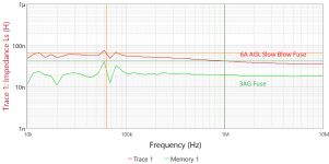
Here's a 3AG -- 20nH and 6A Slo-Blo
Attachments
Last edited:
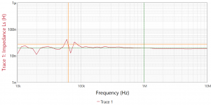
I used Quasimodo (naturally) to measure a 5mmX20mm 5 ampere slow-blow fuse.
With Cx=10.1nF {measured on a DER EE 5000 and also on an AADE LC-meter II}, and two 12-inch crocodile clip jumper wires between the fuse and the bellringer jig
Subtracting the two gives L_fuse = 0.1 uH which is in rough agreement with other people's measurements.
The good news for audio equipment builders is: the inductance of the fuse "F1" is a tiny, tiny addition to the self-inductance of the transformer secondary. Even if you omit the fuse from your wiring harness when you tune your secondary snubber(s) with Quasimodo, the difference will be small. Aaaah.
_
With Cx=10.1nF {measured on a DER EE 5000 and also on an AADE LC-meter II}, and two 12-inch crocodile clip jumper wires between the fuse and the bellringer jig
- Fuse shorted: Osc_Freq = 1.43 MHz ... thus L_total = 1.24 uH
- Fuse intact: Osc_Freq = 1.37 MHz ... thus L_total = 1.34 uH
The good news for audio equipment builders is: the inductance of the fuse "F1" is a tiny, tiny addition to the self-inductance of the transformer secondary. Even if you omit the fuse from your wiring harness when you tune your secondary snubber(s) with Quasimodo, the difference will be small. Aaaah.
_
“golden ears” claims to be able to hear the fuse!I used Quasimodo (naturally) to measure a 5mmX20mm 5 ampere slow-blow fuse.
With Cx=10.1nF {measured on a DER EE 5000 and also on an AADE LC-meter II}, and two 12-inch crocodile clip jumper wires between the fuse and the bellringer jig
Subtracting the two gives L_fuse = 0.1 uH which is in rough agreement with other people's measurements.
- Fuse shorted: Osc_Freq = 1.43 MHz ... thus L_total = 1.24 uH
- Fuse intact: Osc_Freq = 1.37 MHz ... thus L_total = 1.34 uH
The good news for audio equipment builders is: the inductance of the fuse "F1" is a tiny, tiny addition to the self-inductance of the transformer secondary. Even if you omit the fuse from your wiring harness when you tune your secondary snubber(s) with Quasimodo, the difference will be small. Aaaah.
_
“golden ears” claims to be able to hear the fuse!
An especially easy claim to test. Experiment 1: (double blind) someone's wife installs either the fuse, or a solid copper rod of the same diameter, into the fuse holder. Takes a few digital photos with timestamp. Listening panel, listens. Experiment 2: same person swaps them, replacing fuse with copper rod or vice versa. Takes a few more digital photos with timestamp. Listening panel, listens. Experimenter asks panel, which did you prefer? After votes are tallied, wife shows digital photos with timstamps.
Be sure to wipe the fuse and the copper rod, with your favorite contact cleaner (Cramolin? DeOxit? Unicorn tears?), before installation. If you believe in burnishing, burnish.
- Home
- Amplifiers
- Power Supplies
- Simple, no-math transformer snubber using Quasimodo test-jig