I can assure you I've read every post in this thread. Did I really miss it?
(Post #555 also asks the question, but there's no answer. Post #649 states that there were 4 design frequencies, but not why a 4-position dip-switch was used.)
Anyway, it doesn't really matter. Curiosity just got the better of me....
(Post #555 also asks the question, but there's no answer. Post #649 states that there were 4 design frequencies, but not why a 4-position dip-switch was used.)
Anyway, it doesn't really matter. Curiosity just got the better of me....
There have been a couple of attempts to set up public and/or privately curated tables of Quasimodo results, but none have really taken off.
Given the recent interest, I'm going to make a 3rd attempt with the lowest-possible-cost-of-entry: a diyAudio thread for results ONLY.
http://www.diyaudio.com/forums/power-supplies/313202-quasimodo-results.html#post5206650
If it gets a reasonable amount of traction, perhaps we can get it made sticky.
Only problem is...that takes all the fun out of it. Building the Quasimodo and Cheapomodo were real learning experiences for me. I would hate to see others miss out on that.
What type of capacitors are preferred for use in snubber networks? Got a link to mouser or digikey? I checked the BOM but it doesn't specify other than capacitance.
"the EPCOS B32529 series is a favorite." It's in the manual.
Any film capacitor with sufficient voltage rating will certainly work. Others might too, but at these values there's little reason not to use a film. The purists will no doubt go on to say "only polypropylene", but I don't subscribe to that. I think polyester is perfectly adequate for this application.
I've been using Wima MKS2 for secondaries up to 30V (nominal):
MKS2C031501A00KC00 WIMA | Mouser Ireland
MKS4 for up to 45V (nominal):
MKS4D031502B00JSSD WIMA | Mouser Ireland
and Wurth FTXX for up to 225V (nominal):
890334022017CS Wurth Electronics | Mouser Ireland
I also used some 400V Dayton polypropylenes from the junk drawer. It's always nice to take something out of the junk drawer, rather than constantly stuffing more things in....")
I've been using Wima MKS2 for secondaries up to 30V (nominal):
MKS2C031501A00KC00 WIMA | Mouser Ireland
MKS4 for up to 45V (nominal):
MKS4D031502B00JSSD WIMA | Mouser Ireland
and Wurth FTXX for up to 225V (nominal):
890334022017CS Wurth Electronics | Mouser Ireland
I also used some 400V Dayton polypropylenes from the junk drawer. It's always nice to take something out of the junk drawer, rather than constantly stuffing more things in....
The great thing about "bell ringer" test jigs with snubbers is, that you can directly observe how well or how poorly this specific individual snubbber actually works. You can install candidate capacitor #1, turn on the bellringer, and dial the Rsnub to find the least objectionable waveform. If you're happy, boom! The job is done.
If you're not happy, if the least objectionable waveform is still objectionable, then remove capacitor #1 and install candidate capacitor #2 in its place. Turn on the bellringer and dial the Rsnub to find the least objectionable waveform with this new capacitor. Happy? If so, have a pint. If not, proceed on to candidate capacitor #3, and so forth. Install cap, turn on the bellringer, twirl the potentiometer, look at the scope trace, and ask yourself: is this good enough, in my opinion?
Another, completely opposite, approach would be: choose transformer snubbing capacitor types (and even capacitor values!) through comparative listening tests. At least one person here on this thread, reported that s/he heard differences when swapping equal-valued snubber capacitors made by different manufacturers. I have not tried this experiment myself so I have no data to report.
Hi Mark and all,
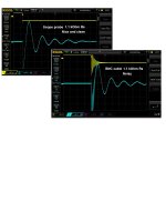
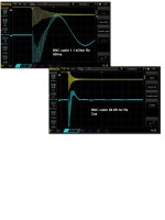
Need your advice and it might be off the subject but related to Quasimodo. I boxed it long time ago and used scope probes with no issues. Started to use BNC to BNC cable and I see signal reflection on scope. Any advice how to defeat that efficiently? Thank you.
Need your advice and it might be off the subject but related to Quasimodo. I boxed it long time ago and used scope probes with no issues. Started to use BNC to BNC cable and I see signal reflection on scope. Any advice how to defeat that efficiently? Thank you.
Attachments
Hi Mark, I probably confused you with my question.
I have varies probes and no issue with them at all. They all works with Quasimodo perfectly fine.
Question is for cable with BNC to BNC connectors. I installed Quasimodo into box with BNC outputs for CH1 and CH2. Probably Scope Probes use active impedance matching and my BNC cables are 50 Ohm steady.
Two things I would check:
Is the cable terminated into the right impedance?
Are the connectors niece and snug and making good electrical connection?
Hope that's at least a start. Good luck
Phil
-edit - I think you have it, Alex, with impedance matching. Terminate the cables into 50 ohms.
Is the cable terminated into the right impedance?
Are the connectors niece and snug and making good electrical connection?
Hope that's at least a start. Good luck
Phil
-edit - I think you have it, Alex, with impedance matching. Terminate the cables into 50 ohms.
Two things I would check:
Is the cable terminated into the right impedance?
Are the connectors niece and snug and making good electrical connection?
Hope that's at least a start. Good luck
Phil
-edit - I think you have it, Alex, with impedance matching. Terminate the cables into 50 ohms.
Hi Phil,
I use both ends industrially made BNC RG58 coax. It is 50 ohm impedance and 2 m in length
 . All connectors are tight.
You measured 50R between the center pin and shield on that disconnected BNC interconnect?
BK
No. What is the point to measure that? 50 Ohm is impedance, not resistance. RG58 coax is 50 Ohm impedance by spec.
Point is depending your scope/settings you might need to terminate the connection with a feed through connector, etc.
BK
It is infinitely.
Do you have the scope set to 50ohms? Most of them will default to 1Mohms.
(They also have a much lower max input voltage at the 50ohm setting. Depending on the transformer you're measuring, you may need to leave it on the 1Mohm setting and put a 1Mohm resistor in series with the cable.)
Cheers,
Jeff.
(They also have a much lower max input voltage at the 50ohm setting. Depending on the transformer you're measuring, you may need to leave it on the 1Mohm setting and put a 1Mohm resistor in series with the cable.)
Cheers,
Jeff.
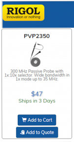
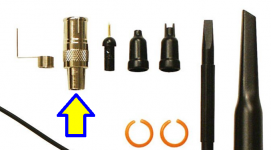
I purchased object #1 from post_1271. It includes a little bag of add-on goodies. One of them is an adapter which lets you plug the scope probe straight into a BNC male socket. It makes solid connection to both the tip needle and the ground collar. See figure_1 below.
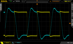
I used that adapter on a BNC male, to make the measurement shown in figure_2 below. (It's an opamp not a Quasimodo!) Notice that the horizontal scale is 200 nsec/div --- considerably faster than the 500 nsec/div rate in the pictures of misbehaving traces in post 1270 above.
_
I used that adapter on a BNC male, to make the measurement shown in figure_2 below. (It's an opamp not a Quasimodo!) Notice that the horizontal scale is 200 nsec/div --- considerably faster than the 500 nsec/div rate in the pictures of misbehaving traces in post 1270 above.
_
Attachments
Last edited:
- Home
- Amplifiers
- Power Supplies
- Simple, no-math transformer snubber using Quasimodo test-jig