I need a 450V voltage reference for the feedback circuit of a series regulator. I know of two simple methods; zeners and resistors, loaded with a CCS to get the proper operating point or developed voltage respectively. What method is regarded best?
I understand both have noise, but bypassing should take care of that for the most part. If there are better alternatives, I'm all ears.
I understand both have noise, but bypassing should take care of that for the most part. If there are better alternatives, I'm all ears.
Why do you use such a high reference voltage: in general, the error amplifier is made to operate at a conveniently low voltage, where optimization of noise, parasitic effects, etc can be carried out easily.
At such a high voltage, both solutions will be inconvenient: you will need a stack of multiple high voltage zeners (avalanche), having relatively poor performance, and the CCS option will be sensitive to the tiniest parasitic conductance anywhere near.
Plus, the signal part of the regulator will have to be 450V-rated, and high voltage devices tend to be a tradeoff between voltage and all the rest, meaning their performances will be rather poor
Thanks for the responses. The schematic below might shed some light as to why I want such a high reference. I'm still pretty new to these kind of PSU's so it;s all a learning experience. The only way I know of to make the error amp work at lower voltages, is take the output voltage and lower it by means of a voltage divider and bypass the upper part of the resistor network. Or are there 'better' schematics to achieve the same thing?
@Pergo: I didn't know this device. I'll look into it.

@Pergo: I didn't know this device. I'll look into it.
I would have thought a more conventional discrete arrangement would be simpler. The error amp is ground referenced and uses a low voltage zener as a reference. Floating a 741 like that looks a recipe for problems tbh, its so easy to kill the IC with transients etc.
This shows the basic idea. Its a common and standard topology thats easily scaleable and tweakable.
This shows the basic idea. Its a common and standard topology thats easily scaleable and tweakable.
Attachments
if you need current, the Maida regulator is OK
http://www.diyaudio.com/forums/tubes-valves/209067-21st-century-maida-regulator.html
http://www.diyaudio.com/forums/tubes-valves/209067-21st-century-maida-regulator.html
I would have thought a more conventional discrete arrangement would be simpler. The error amp is ground referenced and uses a low voltage zener as a reference. Floating a 741 like that looks a recipe for problems tbh, its so easy to kill the IC with transients etc.
This shows the basic idea. Its a common and standard topology thats easily scaleable and tweakable.
Thanks, I'll look into the schematic. As far as the 741 is concerned, the opamp's powerrails are held at a 20V differential by the zener, and the four diodes at the input prevent the inputs from ever going past the powerrails. How would it be able to get damaged?
if you need current, the Maida regulator is OK
http://www.diyaudio.com/forums/tubes-valves/209067-21st-century-maida-regulator.html
I've worked with the original Maida circuit before in a preamp project with great results. But this puppy needs to go into my power-amp, with peaks up to 800mA + the 60mA idle current (parallel-push-pull). Both Maida configurations would exploded AFAIK, since it's not only the pass MOSFET that has to handle the current.
The awkward part of your schematic lies in the supply/reference via the zener string and CCS.
You can rearrange it somewhat differently and eliminate practically all the issues: you can reference the + opamp supply to the output, and generate the zener current with a simple resistor: this will work, because the output voltage is constant, and will therefore generate a constant current.
You can then sample the output voltage (negative side) with a conventional voltage divider.
It looks somewhat incestuous, but it actually works because of the gain of the error amplifier.
There may be some start-up issues, but they can be solved with a diode and a few additional components
That is basically what I do in the Simple Series Reg, except it is discrete.
Doing the same with an opamp is certainly possible.
The big advantage of such an approach is that the only components in the control part actually seing the full input voltage are just resistors, which means it very safe
Thanks, I'll look into the schematic. As far as the 741 is concerned, the opamp's powerrails are held at a 20V differential by the zener, and the four diodes at the input prevent the inputs from ever going past the powerrails. How would it be able to get damaged?
Would the diodes protect in all circumstances and conditions ? What if there were a glitch on the output, something pulling it down for even a few microseconds. Pin 2 of the opamp would be heading toward 0 volts and the nature of transients are that rise and fall times can be very quick indeed. What would the differential be between pin 2 and all the other pins during that instant ? Its conditions like that which cause unexplained failures. Similarly the junction capacitance of semiconductors (diodes !) can couple significant energy if a transient glitch appears. It may happen only very infrequently but if its a possible source of failure then its no good. The FET has very high junction capacitance and could be a prime suspect under adverse conditions.
The circuit just has that "look" about it. That its to fussy, could be prone to problems.
I don't quite follow. I get the part about the constant zener current, which would negate the use of a CCS, but you lost me with the opamp. Do you mean it'still floats on top of the high voltage zeners?The awkward part of your schematic lies in the supply/reference via the zener string and CCS.
You can rearrange it somewhat differently and eliminate practically all the issues: you can reference the + opamp supply to the output, and generate the zener current with a simple resistor: this will work, because the output voltage is constant, and will therefore generate a constant current.
You can then sample the output voltage (negative side) with a conventional voltage divider.
It looks somewhat incestuous, but it actually works because of the gain of the error amplifier.
There may be some start-up issues, but they can be solved with a diode and a few additional components
That is basically what I do in the Simple Series Reg, except it is discrete.
Doing the same with an opamp is certainly possible.
The big advantage of such an approach is that the only components in the control part actually seing the full input voltage are just resistors, which means it very safe
Would the diodes protect in all circumstances and conditions ? What if there were a glitch on the output, something pulling it down for even a few microseconds. Pin 2 of the opamp would be heading toward 0 volts and the nature of transients are that rise and fall times can be very quick indeed. What would the differential be between pin 2 and all the other pins during that instant ? Its conditions like that which cause unexplained failures. Similarly the junction capacitance of semiconductors (diodes !) can couple significant energy if a transient glitch appears. It may happen only very infrequently but if its a possible source of failure then its no good. The FET has very high junction capacitance and could be a prime suspect under adverse conditions.
The circuit just has that "look" about it. That its to fussy, could be prone to problems.
Yes, I have to admit I'm still a bit naive to these things and tend look at e.g. a diode as an 'ideal' component. Thanks for the reality check.
A picture is worth a thousand words.I don't quite follow. I get the part about the constant zener current, which would negate the use of a CCS, but you lost me with the opamp. Do you mean it'still floats on top of the high voltage zeners?
Here is what I mean (it is just the plain vanilla concept, without additional filtering, protection and various bells and whistles):
Attachments
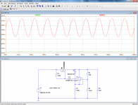
Thanks a million for taking the time to sketch up the schematic! It makes things a lot more clear. I've copied it in LTSpice, but with the components I have at hand (MOSFET, opamps LM741 and TL072), I can't get it to regulate properly. I not sure what I'm doing wrong.
Edit: I just replaced the opamp with the LT1077 you're using and it works as it should. Is the opamp used this critical or is my model incomplete??

Edit: I just replaced the opamp with the LT1077 you're using and it works as it should. Is the opamp used this critical or is my model incomplete??
Last edited:
The LT1077 is a micropower opamp. For a 741 you may need to reduce R1 to allow for the higher opamp current and also reduce the divider network by perhaps a factor of 10 to allow for the higher input bias currents of a 741. The TL071 can keep the didvider network as it is.
The opamp needs to include the GND in its input common mode range (this could easily be eliminated with an additional divider).Edit: I just replaced the opamp with the LT1077 you're using and it works as it should. Is the opamp used this critical or is my model incomplete??
Other than that, most opamps should work, half a LM358 for instance.
Make sure the current through R2 is higher than its supply current.
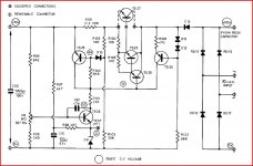
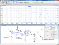
Here is a working version, dressed up with protections, bypasses and properly compensated.
The DC output resistance is ~110µΩ, and the ripple rejection is 96dB @100Hz.
None of the components are critical, and you could opt for 10V or 20V zeners without problems.
The circuit will be very robust against spikes, power-on or off conditions, load dumps, but it isn't protected against shorts (that could be added without too much difficulty)
Attachments
I can't thank you guys enough!
Mooly, you're right. For some reason, my TL072 model needs way more current (including the zener operating point) to operate than is specified on the datasheet. Lowering R1 enough got it working.
Elvee... wow... awesome. Do you consider the design worthy for breadboarding?? My fingers are itching
Mooly, you're right. For some reason, my TL072 model needs way more current (including the zener operating point) to operate than is specified on the datasheet. Lowering R1 enough got it working.
Elvee... wow... awesome. Do you consider the design worthy for breadboarding?? My fingers are itching
Last edited:
The TLO72 is not supposed to work in the circuit as is, it doesn't include GND in its common-modeFor some reason, my TL072 model needs way more current (including the zener operating point) to operate than is specified on the datasheet. Lowering R1 enough got it working.
I think so, find a proper opamp like the LM358, simulate it and breadboard it (carefully, this HV)Elvee... wow... awesome. Do you consider the design worthy for breadboarding?? My fingers are itching
The TLO72 is not supposed to work in the circuit as is, it doesn't include GND in its common-mode
I think so, find a proper opamp like the LM358, simulate it and breadboard it (carefully, this HV)
Yeah, from memory I thought TL072 did C-M to GND, but it includes Vcc, not GND

Am I correct to assume Q1 is there for any startup issues??
P.s. I bought a LT1077 and got some LM358's in the mail. I'll keep you posted! Thanks again.
Last edited:
No, Q1 serves to improve the ripple rejection.Am I correct to assume Q1 is there for any startup issues??
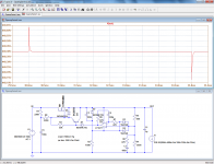
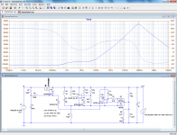
If you choose a dual opamp like the LM358, you can use the unused half as a self regulator (one more layer of incestry!).
Since it is much more perfect than a plain zener, you can now dispense with the transistor and get a better line regulation, -107dB in this case. The ripple rejection remains the same at -96dB, because it caused by the MOS capacitances leaking the ripple directly into the output.
It also gives more freedom in the choice of the zener, because the internal supply is now set by a resistors ratio.
You could use a temperature-compensated one, or a bandgap reference.
Attachments
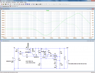
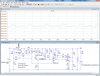
With a single supplementary transistor, it is possible to implement a current limit (here 800mA), SOA protection and thermal overload combo (the transistor has to be in contact with the heatsink).
At low temperatures, it will keep the dissipation in the MOS <150W, decreasing at higher temperatures.
At low temperatures, it will keep the dissipation in the MOS <150W, decreasing at higher temperatures.
Attachments
- Status
- This old topic is closed. If you want to reopen this topic, contact a moderator using the "Report Post" button.
- Home
- Amplifiers
- Power Supplies
- CCS + Zeners or resistors for 450V reference