Hi All.
I have a McCurdy Phono Pre (the unit is from the late 70' or early 80's.) that initially had a lot of noise and AC oscillation in the audio path. I did a complete cap change (both phono cards and power supply) and that sorted things out…mostly.
This unit has a 48v power supply. Recently, As an experiment, a friend and I disconnected the original power supply and connected a 48v wall wart power supply instead. Well, the noise floor dropped about 20db.
As things stand now with the original power supply, there is still a little AC in the 48v DC coming out of the power supply. But, more worrisome is an ultra low frequency (below 20hz) that modulates the DC and the extra AC component. I can eliminate the ultra low frequency with a high pass filter but, of course, it shouldn't be there in the first place.
Is it worth replacing components with higher grade/newer ones or is there a "silver bullet" component that can be replaced?
The supply is small enough (and there is enough room in the case) to consider replacing it completely too.
The noise floor with the original power supply floats between -57db and -67db.
The noise floor with the 48v wall wart supply is about -80db.
and, for comparison, my 90$ Project phono pre has a noise floor of -90db.
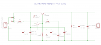
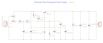
Also, I've attached schematic that I created. I hope that it makes sense.
Parts
D1, D2 = 060
D3 = 1N4757
R1, R2 = 910Ohm
R3 = 100Ohm
R4 = 47kOhm
R5 = 10kOhm
Q1 = 2N3054
Q2 = 2N2102
C1 = 47uf 63v
C2 = (Film)? 0.01M 630v
C3 = 100 uf 63v
C4 = 220uf 63v
C5 = 1000uf 63v
C6 = (film?) 0.1M 250v
C7 = (Ceramic?) 01u
Thanks for your time,
Mitch
I have a McCurdy Phono Pre (the unit is from the late 70' or early 80's.) that initially had a lot of noise and AC oscillation in the audio path. I did a complete cap change (both phono cards and power supply) and that sorted things out…mostly.
This unit has a 48v power supply. Recently, As an experiment, a friend and I disconnected the original power supply and connected a 48v wall wart power supply instead. Well, the noise floor dropped about 20db.
As things stand now with the original power supply, there is still a little AC in the 48v DC coming out of the power supply. But, more worrisome is an ultra low frequency (below 20hz) that modulates the DC and the extra AC component. I can eliminate the ultra low frequency with a high pass filter but, of course, it shouldn't be there in the first place.
Is it worth replacing components with higher grade/newer ones or is there a "silver bullet" component that can be replaced?
The supply is small enough (and there is enough room in the case) to consider replacing it completely too.
The noise floor with the original power supply floats between -57db and -67db.
The noise floor with the 48v wall wart supply is about -80db.
and, for comparison, my 90$ Project phono pre has a noise floor of -90db.
Also, I've attached schematic that I created. I hope that it makes sense.
Parts
D1, D2 = 060
D3 = 1N4757
R1, R2 = 910Ohm
R3 = 100Ohm
R4 = 47kOhm
R5 = 10kOhm
Q1 = 2N3054
Q2 = 2N2102
C1 = 47uf 63v
C2 = (Film)? 0.01M 630v
C3 = 100 uf 63v
C4 = 220uf 63v
C5 = 1000uf 63v
C6 = (film?) 0.1M 250v
C7 = (Ceramic?) 01u
Thanks for your time,
Mitch
Hi Rolf and Alayn91.
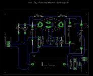
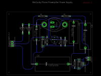
A schematic for the power supply was not available so I created it based on the circuit board. Here is the layout of the circuit board.
Q1 has "2N3054 RCA CH 7629" printed on it.
Q2 has "2N2102 612" printed on it. Any search results return an NPN Bipolar transistor.
A schematic for the power supply was not available so I created it based on the circuit board. Here is the layout of the circuit board.
Q1 has "2N3054 RCA CH 7629" printed on it.
Q2 has "2N2102 612" printed on it. Any search results return an NPN Bipolar transistor.
Attachments
Very,very strange.The power supply will not work as it is.There are so many faults that I wonder who on Earth managed to make up this mess...
I've drawn another way it could be designed.Note that this second drawing is NOT complete-just an illustration of the principle(how the two transistors could be connected together)
I've drawn another way it could be designed.Note that this second drawing is NOT complete-just an illustration of the principle(how the two transistors could be connected together)
Attachments
Hey Rolf.
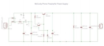
I went back to the circuit board and verified that it was me who made the mess . I missed a trace and the 2N2102 flipped. Hopefully the revised schematic makes more sense.
I went back to the circuit board and verified that it was me who made the mess
. I missed a trace and the 2N2102 flipped. Hopefully the revised schematic makes more sense.Attachments
It's not really regulated: there's no feedback, so it's more of an amplified zener arrangement. Perhaps there's some interaction between the preamp and power supply that results in "motorboating".
Any 3-terminal regulator should provide much better regulation. The LM317HV might be the best suited.
Any 3-terminal regulator should provide much better regulation. The LM317HV might be the best suited.
Rolf-thanks for helping me sort out the schematic.
KatieandDad-I did test the supply for AC (but only with a multimeter) and found that, from directly after the diodes to the output, there is 00.1 vac. When my friend quickly looked at the supply output on an oscilloscope the trace AC and oscillating sub-frequency was there already. I guess that the phono boards are amplifying this signal as well as the intended audio.
My phono board thread is here.
Dangus-I'll look into the LM317HV. Do you think that would also help the noise floor?
I would expect it to be comparable or better than the wall wart. Depending on what was inside that wall wart... switching supplies will have some high frequency ripple. Linear Tech had some 3-terminal regulators that performed even better, but I don't know if they make a high voltage version. Not that the high voltage rating is extremely critical, since in normal operation it should only be dropping a moderate voltage. I guess the worst cases would be a shorted output, or if the preamp had some big caps to charge up.
Perhaps there's a way to put a transistor upstream of the regulator so as to limit the maximum voltage that could ever be dropped across the regulator. Application notes for 3-terminal regulators may show something like this.notes.
Perhaps there's a way to put a transistor upstream of the regulator so as to limit the maximum voltage that could ever be dropped across the regulator. Application notes for 3-terminal regulators may show something like this.notes.
A simple emitter follower can actually be very good.I would have expected the original to be too,especially since it uses extensive decoupling(R-C-R-C) of the feed to the zener.Have you tried replacing the zener?
Simple Voltage Regulators Part 1: Noise - [English]
Simple Voltage Regulators Part 1: Noise - [English]
Sorry, I've been away from the computer.
I haven't replaced anything yet (except for the electrolytic caps) which did resolve the original noise issue and brought the noise floor down to its existing level. I actually have access to another (same model) McCurdy Phono pre. It's an early 80's model but exactly the same in layout and spec. That one is quieter then mine but the wall wart experiment brought my noise floor down to a comparable level. Still both units were beaten (overall noise floor) by my 90$ Project phono pre.
As for replacement, I was hoping to suss-out the best candidates for replacement and order everything at one time from Mouser.
Thanks for the article Rolf.
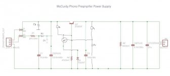
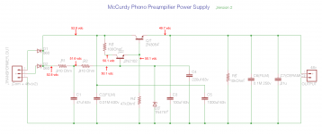
I don't have the equipment to do an in-depth assessment. I do have a Multimeter and with that I've added as many measurements as I could to the schematic.
I hope it's helpful.
(I measured the output as 49.7v but the because the specs stipulate 48v I labeled the schematic as such).
I haven't replaced anything yet (except for the electrolytic caps) which did resolve the original noise issue and brought the noise floor down to its existing level. I actually have access to another (same model) McCurdy Phono pre. It's an early 80's model but exactly the same in layout and spec. That one is quieter then mine but the wall wart experiment brought my noise floor down to a comparable level. Still both units were beaten (overall noise floor) by my 90$ Project phono pre.
As for replacement, I was hoping to suss-out the best candidates for replacement and order everything at one time from Mouser.
Thanks for the article Rolf.
I don't have the equipment to do an in-depth assessment. I do have a Multimeter and with that I've added as many measurements as I could to the schematic.
I hope it's helpful.
(I measured the output as 49.7v but the because the specs stipulate 48v I labeled the schematic as such).
Attachments
Last edited:
- Status
- This old topic is closed. If you want to reopen this topic, contact a moderator using the "Report Post" button.
- Home
- Amplifiers
- Power Supplies
- 48v Power supply for McCurdy Phono Pre