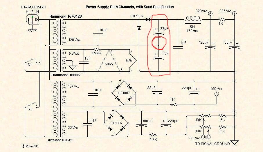
Hello everyone...I'm in need of some help so I'm posting here for the first time. I recently completed building Poindexter's 2006 6V6 Musical Machine. When I powered up the heaters the tubes lit up and began warming. After the tubes warmed up I flipped the power switch and the fuse instantly blew (using a 2A slo-blo). I have now rebuilt the amplifier 6 times. I finally discovered what is causing the fuse to blow (I blew 12 fuses fuses and 2 Caps before tracking down this problem). The problem is in the Main Power Supply Circuit, it is occuring on the two 33uf/450v Capacitors wired in series. Attached is the schematic with the location of the problem circled. I've tried relentlessly to contact Poindexter at every email address I can find....all are no longer working, AudioTropic's website is no longer valid, and I've read Poinzie's DIY Audio Pages completely through many times...I can still not find an answer to my problem. I'm hoping someone can shed light on this situation. The HV Iron used is the Hammond Transformer named in the schematic (167G120) it is actually a 120V CT. I'm guessing the CT connects to ground as with the Filament Transformer....but the HV Transformer's CT is missing from the Schematic. Do I leave it unconnected??? That wouldn't produce the full 120Vac though.
I really need to know why this circuit is overloading and blowing a fuse when the second lead from the transformer connects to in between these two capacitors. The Cap's get extremely hot...I actually had two 33uf/400v Caps blow up before the fuse blew...so I've been using 450v Caps now and have not had that problem. Please, someone who is more experienced that I....could you shed some light on why this could occur? Am I doing something wrong somewhere else that is causing this? All the other circuits test and work great when powered up (I built and tested all separately after the first build resulted in a no go). I'm getting frustrated and now searching for different Voltage Doubler circuits that I can build with this transformer....I don't have the funds in this project at the moment to buy a different transformer so I NEED to make this one work for the time being. Any suggestions, ideas, or remarks will be greatly appreciated! Thank you everyone in advanced for you time and help!
- Kelly
First: in place of blown unnecessarily fuses, use a serial lamp (incandescent one) in place of the fuse so any overload will be easily seen by the light of the lamp. The lamp about the same power of the DUT (device under test).
Second, try a NTC in series to the trafo's secondary, may be the first charge pulse will be causing the headache.
Second, try a NTC in series to the trafo's secondary, may be the first charge pulse will be causing the headache.
Last edited:
I had a look at Ponzies schematic ... you mentioned a CT on HV secondary DO NOT set to ground ,tie them together and insulate ...
I am interested in a Voltage doubler for a guitar amp I'm collecting parts for right now. There are several schematics for voltage doublers in the forum just seach using the seach button rt hand end of tool bar.
Regards, Elwood
I am interested in a Voltage doubler for a guitar amp I'm collecting parts for right now. There are several schematics for voltage doublers in the forum just seach using the seach button rt hand end of tool bar.
Regards, Elwood
Thanks everyone for the input. I do not have the CT connected to anything so that's good (check). I've changed the diodes each time I rebuilt this circuit, however I have not changed the type of diode. I am currently using the UF1007s, should I try a different type such as UF4007?? I had not considered the diodes bc they are working in the other circuits. I checked the Caps polarity....I've got them wired just as shown in the schematic...so that's correct (check). I've even used different caps thinking that was the problem.
So, I've rebuilt the circuit and tested it by building it one component at a time, powering on, testing with volt meter for proper voltage, power off and repeat. As soon as I connect two 33uf/450v Polarized Electrolytic Capacitors in series as shown, BOOM...Capacitors overheat, fuse blows. How can I rule out a bad transformer? With nothing connected, the transformer is giving correct voltages and seems to be operating correctly. Any additional thoughts??
So, I've rebuilt the circuit and tested it by building it one component at a time, powering on, testing with volt meter for proper voltage, power off and repeat. As soon as I connect two 33uf/450v Polarized Electrolytic Capacitors in series as shown, BOOM...Capacitors overheat, fuse blows. How can I rule out a bad transformer? With nothing connected, the transformer is giving correct voltages and seems to be operating correctly. Any additional thoughts??
Frank,
To be honest, I am not sure of that as this is the first project I've ever done that used diodes. I read that the white stripe around the base of the diode denotes the negative side. Based on this info, this is how I have connected them all. Before I go turning the diodes around, Ill wait to for your reply. It would e really nice if its something this dumb (and would not surprise me either). So, which end of the diode has the white stripe around the base, negative or positive?
To be honest, I am not sure of that as this is the first project I've ever done that used diodes. I read that the white stripe around the base of the diode denotes the negative side. Based on this info, this is how I have connected them all. Before I go turning the diodes around, Ill wait to for your reply. It would e really nice if its something this dumb (and would not surprise me either). So, which end of the diode has the white stripe around the base, negative or positive?
Are you SURE that the diodes aren't installed backwards?
Alright.....I feel dumb now. Thanks Frank! You're the man for pointing out diode polarity. i honestly had not thought about the diodes at all. i just kept connecting new diodes each time I'd wire the circuit and I connected them the same way (the wrong way). One of the diodes was backwards. This has solved my problem. On to finish building this amp! I really appreciate everyone's help, time and input. If only I had posted this a couple days ago...could have saved me all the troubles....thanks again.
Frank,
To be honest, I am not sure of that as this is the first project I've ever done that used diodes. I read that the white stripe around the base of the diode denotes the negative side. Based on this info, this is how I have connected them all. Before I go turning the diodes around, Ill wait to for your reply. It would e really nice if its something this dumb (and would not surprise me either). So, which end of the diode has the white stripe around the base, negative or positive?
The stripe on a diode denotes the cathode and the other end is the anode , when used as a rectifier the Positive DC will come off of the cathode or the end with the stripe ..... In the Diode symbol the cathode is the end with the line ....
The stripe on a diode denotes the cathode and the other end is the anode , when used as a rectifier the Positive DC will come off of the cathode or the end with the stripe ..... In the Diode symbol the cathode is the end with the line ....
Thanks for the detailed response. Yes that's what I figured out after Frank mentioned the diodes, taking a closer look I had been connecting one of them backwards to the symbol on the schematic. I have not fixed this yet as I had to run an errand but I'm confident this is the entire problem an once corrected I will be good to go!
I am much more knowledgeable when it comes to Car Electronics (12V electrical systems) and have never used diodes before. In cars we use Capacitors, switches, relays, fuses and resistors but not diodes (there may be a use for them but I sure haven't had one). So, I guess you could say I made a "rookie mistake"! However, I am trying to figure out what was happening (I like to learn from my mistakes). When the fuse kept blowing and the caps overheating that is a prime sign of something shorting out in automotive electronics...is this essentially what was happening by having the diode connected incorrectly - shorting out?? If anyone can shed some more light on this it would be greatly appreciated...thanks!
with one diode reversed you were probably reverse biasing the Filter caps which would cause them to heat up and/or explode , and possibly shorting the PSU through the diodes .....
The only place I know if in a Car that uses a Diode is inline with the Positive Battery terminal , it protects against installing the Battery backwards ....
The only place I know if in a Car that uses a Diode is inline with the Positive Battery terminal , it protects against installing the Battery backwards ....
Frank, Minion....thank you for everything! I knew a second set of "eyes" could help identify my problem, and I really do appreciate the in depth explanations, as Frank said...I learned something. I finished the 2006 Musical Machine last night...or should I say this morning around 1am. It sounds amazing and works like a charm. It's actually a lot louder than I had anticipated (which is great). Of course tube audio always seems louder than solid state. I know my 30W Tube Guitar Amp sounds as loud if not louder than my 50W Solid State.
Since everyone was such a big help, I'm hoping maybe y'all can learn me on something else...lol! The B+ voltage of this amp is supposed to be sending 320Vdc, however Im getting close to 370Vdc. Is there any reason that it is doing this since the circuit is built identical to the schematic above? Also, is this bad for the tubes? What can I do to bring it down if so? I'm think a resistor somewhere....but where? As I said the amp sounds great (No distortion, very clear and crisp audio), I'm running my iPhone thru it and out to some Definitive Technologies speakers rated at 92dB SPL (these are actually my home theater speakers but the most sensitive speakers I have on hand for the time being, some 95 - 97dB SPL Folded Horn Designs are in the works but that's a few weeks a way). As always any advice is appreciated! Thanks.
Since everyone was such a big help, I'm hoping maybe y'all can learn me on something else...lol! The B+ voltage of this amp is supposed to be sending 320Vdc, however Im getting close to 370Vdc. Is there any reason that it is doing this since the circuit is built identical to the schematic above? Also, is this bad for the tubes? What can I do to bring it down if so? I'm think a resistor somewhere....but where? As I said the amp sounds great (No distortion, very clear and crisp audio), I'm running my iPhone thru it and out to some Definitive Technologies speakers rated at 92dB SPL (these are actually my home theater speakers but the most sensitive speakers I have on hand for the time being, some 95 - 97dB SPL Folded Horn Designs are in the works but that's a few weeks a way). As always any advice is appreciated! Thanks.
The 370V are under full load at the supply or only quiscient? If at no load, this kind of supply has a large voltage sag under load.
No load. With all the tubes pulled its at 370Vdc. I didn't think about that...does this mean when there's a load it is probably closer to the 320Vdc? I assumed that the voltages shown on the schematic were under no load, what a volt meter should read when testing the tube sockets. Is this an incorrect assumption?
Ok...something is definitely still off...one tube on each channel is glowing red after a minute or two of listening to music. I swapped the tubes around and it seems to be an issue with those particular sockets....not the tubes themselves. Could this be a result of te much higher voltage? Or does this have something to do with bias, the screen resistor or some other issue?
Just wanted to update on the current voltage situation and the glowing tubes. The plate load resistors called for 60k 4w and 62.5k 4w on the preamp tubes. I was using some NOS Allen Bradley 120k 2w and 130k 2w ran in parallel to achieve the appropriate 60k and 62.5k values....one of the resistors was loose and rotating on its leads, so I just swapped all these AB's out for some brand new modern day Carbon Comp resistors. I also checked the ohm value of the screen resistors on the 6V6's since these are supposed to be 100R...they check out fine. I plugged everything in with the amp upside down so that I could check voltages with it running (under a true load). Voltages check out fine under load...where the schematic (in the first post) shows all four voltages should be A) 320Vdc, B) 305Vdc, C) -160Vdc, and D) -20Vdc, I am getting the following: A) 319-320Vdc, B) 295 - 305Vdc, C) -162Vdc, and D) -19Vdc. I would say that's close enough for comfort! The tubes are no longer glowing red hot. Two of the 6V6's have a faint glow on the plate when the volume is down but once it is turned up, it appears to cool and go away. Not sure what this means or what is causing this....but there is no distortion and the sound is definitely "Musical" as it is supposed to be. I still haven't figured out quite how to adjust the bias correctly, I'm getting completely different voltages from both test points and the bias pots don't seem to bring them where they should be....but that's an issue for a different post in a different section. Overall, for this amp being up and running for less that 24hrs...issues have been minimal if not non-exsistent since I worked out the diode polarity and got the tubes to quit glowing!
If you can post a schematic, then things will go better.
Let´s start assuming the output tubes are OK, and in class A. Then, maximum plate dissipation occurs at no input signal, all the quisient current times plate voltage are wasted in watts, heating the plate. As soon a small signal appears at the grid, some part of the anode heat is converted into audio (AC) output power.
Let´s start assuming the output tubes are OK, and in class A. Then, maximum plate dissipation occurs at no input signal, all the quisient current times plate voltage are wasted in watts, heating the plate. As soon a small signal appears at the grid, some part of the anode heat is converted into audio (AC) output power.
Yes as soon as I get home I will post the entire schematic for this build. The bias test point wiring is a little odd compared to what I have seen in most amps and I think this is where my problems are occuring. I'm unable to get an accurate reading of any kind so the bias is probably way off. I was actually thinking of rewiring this part to give each tube it's own yes point and make things simpler. Stay tuned, and thanks for the help!
- Status
- This old topic is closed. If you want to reopen this topic, contact a moderator using the "Report Post" button.
- Home
- Amplifiers
- Power Supplies
- 6V6 Musical Machine Power Supply Problems