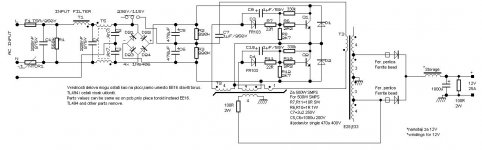
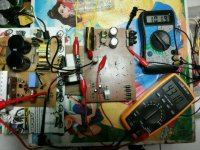
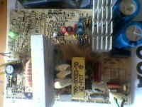
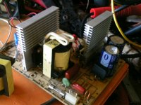
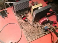
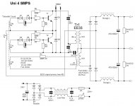
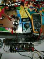
Here's 300W SMPS based on PC power supplies.
A few pictures are not my,i'ts from my friends.
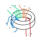
Base drive transformer is toroid from CFL lamp.
Storage core is yelow toroid core from PC PSU too.
They have 0.5V per one turn.You can use more cores glued together.With two cores value is 1V/turn.
You can calculate it this way:
Uout * 2 / number of cores.
This coil is attached after output diodes and before electrolytes.
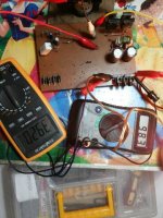
I posted pictures,all is on it")
Schematic is for 12V,for other voltages ee33 have 4V per turn.Resistor on output can be calculated this way: R=Uout/0.02
A few pictures are not my,i'ts from my friends.
Base drive transformer is toroid from CFL lamp.
Storage core is yelow toroid core from PC PSU too.
They have 0.5V per one turn.You can use more cores glued together.With two cores value is 1V/turn.
You can calculate it this way:
Uout * 2 / number of cores.
This coil is attached after output diodes and before electrolytes.
I posted pictures,all is on it
Schematic is for 12V,for other voltages ee33 have 4V per turn.Resistor on output can be calculated this way: R=Uout/0.02
Attachments
-
 Uni4.JPG74.1 KB · Views: 2,231
 -
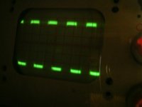 Uce uni4.JPG19.6 KB · Views: 519
 -
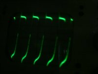 ube uni4 100w.JPG15.2 KB · Views: 603
 -
 300w-load.jpg.jpg35.3 KB · Views: 698
 -
 Noload.jpg.jpg63.5 KB · Views: 764
 -
 Fotografija1233.jpg170.1 KB · Views: 859
 -
 PTDC0004.JPG127.9 KB · Views: 1,767
 -
 BDT.JPG19 KB · Views: 1,815
 -
 IMG_20130729_194812-1.jpg65.2 KB · Views: 1,831
 -
 PTDC0002.JPG115.1 KB · Views: 2,020
Last edited:
I like the simplicity of that project. I have some questions:
- what type are the T1 and T2 transistors ?
- can the base transformer be a "yellow one" too ?
- how thick should be the wires on the base transformer and the main one, if we want to wind one for other output voltage ?
- i have a new etd39 core, can I use it in that project, or will it change everything ?
Greetings, Andrzej
@stewin
ETD49 can be used for 1kW,but with stronger transistors.I calculate 1A of transistor for 40W power out.
Protection is good,but it's better to vind in air core.I tried with 100 turns on solder box (i dont know how to explain this,on this "box" is wounded solder)
You MUST know difference betwen bipolar transistors and fet's.Learn it.
Yes it's ~40khz.
@mayster
T1,T2 any transistor from AT/ATX,13007,13009,2sc2625,2sc4242,etc.Can be any 400-500V,curent 1A for 40W of output power (mje13007 is 8A.This means 8*40=320W smps)
Send me picture of your BDT (base drive transformer)
You can calculate thickness,use 3.5A/mm^2
If you use 300W smps this is ~2A at 160V (half of DC input,this is primary voltage on ee33)
One turn have 2A/3.5A/mm^2= 0.6mm^2
Four turns have 4* smaller diameter (you can use 0.2mm^2)
You can use etd39,and it's enough for ~400W
But you must calculate windings on it.Primary have 160V,and feedback must have 10-12V.
I'll post simple formula tonight.
Formula for calculating transformers:
N=U*1.000.000 / Ae*dB*f*k
N-number of turns
U-input voltage (160V)
Ae-cross section of core (see datasheet)
dB-Inductance in T,for pushpull converters use 2B,for forward and flybac use 1B.B is typicaly 0.2T
f-frequency in khz
k-constant,for sine wave converters (LLC,etc...) use 4.4,for square wave(this smps) use 4.
In this smps peak voltage is voltage at DC output,there's no multiplying by 1,41 like sine wave (classic 50Hz transformer)
My error,inductance is in mT not in TFormula for calculating transformers:
N=U*1.000.000 / Ae*dB*f*k
N-number of turns
U-input voltage (160V)
Ae-cross section of core (see datasheet)
dB-Inductance in T,for pushpull converters use 2B,for forward and flyback use 1B.B is typicaly 0.2T
f-frequency in khz
k-constant,for sine wave converters (LLC,etc...) use 4.4,for square wave(this smps) use 4.
In this smps peak voltage is voltage at DC output,there's no multiplying by 1,41 like sine wave (classic 50Hz transformer)
For 20-40KHz dB = 0,4 to 0,35T; for 40-80KHz dB 0,3 to 0,2T; for >80KHz dB <0,2T
Last edited:
Formula for calculating transformers:
N=U*1.000.000 / Ae*dB*f*k
N-number of turns
U-input voltage (160V)
Ae-cross section of core (see datasheet)
dB-Inductance in T,for pushpull converters use 2B,for forward and flybac use 1B.B is typicaly 0.2T
f-frequency in khz
k-constant,for sine wave converters (LLC,etc...) use 4.4,for square wave(this smps) use 4.
In this smps peak voltage is voltage at DC output,there's no multiplying by 1,41 like sine wave (classic 50Hz transformer)
Ok, what I'm doing wrong ? My earlier mistake, i have a etd34 core, but that's no problem.
I want to calculate the primary winding, and so on:
N = 160 V * 1000000 / 97,1 * 0,4 * 40 * 4
N = 25746 ... what's wrong ? I thought about the kHz ant that would be ~25,7 turns - that's not too small ?
The second problem i have - the output coils (before the electrolytic capacitors) - how big should they be ? should they be wound together on one core ?
Perhaps inverting the feedback winding ?So... don't working
The driver transformer wound like on the picture. Primary on the main transformer 26 turns. feedback winding 3 turns.
Also I wonder ,are C1 and C2 polarised in the right direction.The diodes in parallel block the voltage in the direction the electrolytics can handle.
Mona
- Status
- This old topic is closed. If you want to reopen this topic, contact a moderator using the "Report Post" button.
- Home
- Amplifiers
- Power Supplies
- 300W SMPS for amp. from PC PSU