I know there are a lot of threads about PSUs and capacitor sizes etc. but I wanted to know if anyone has 'scoped' the +-DC from the PSU when running their chip amps.
Peter Daniel from audiosector.com uses only 1500uF caps per rail right at the chip, others use thousands of uF on the PSU board and others use snubberized supplies. Everyone claiming their particular setup is 'the best' implementation.
Has anyone out there built several different PSUs and tested them with the same chip amp? A test like putting a 25Hz sine wave into the input and see what the DC is doing at different volumes, then 50Hz, 100Hz, 200HZ, 400Hz etc.
I didn't scope it but I did record it with my Sony PCM recorder (96k sample rate). I put some plots up on this thread - Possibly the most frugal high-end sounding amp? - Page 3
From the results of these recordings, I've gone over to massively paralleled banks of small caps
From the results of these recordings, I've gone over to massively paralleled banks of small caps
Basically, what you'll see on the rails is an increase in ripple proportional to the current drawn from the power supply, combined with an inverse proportionality to the amount of reservoir capacitance.
And they may all be correct.
Different circuits and chip amps may have different PSRRs. Your test method isn't invalid, but what is more important than ps DC output is the effect on chip amp output, i.e. with a clean 25Hz 1V signal in, and a gain of 10, the chip amp should output a clean 25Hz 10V signal. Increasing the volume (which increases the load on the ps) will eventually cause the output to distort (ripple exceeds what the circuit can handle) or clip (the supply has reached its physical limit).
I'm not an expert, though, so there's sure to be holes in that explanation.
But of course.Everyone claiming their particular setup is 'the best' implementation.
And they may all be correct.
Different circuits and chip amps may have different PSRRs. Your test method isn't invalid, but what is more important than ps DC output is the effect on chip amp output, i.e. with a clean 25Hz 1V signal in, and a gain of 10, the chip amp should output a clean 25Hz 10V signal. Increasing the volume (which increases the load on the ps) will eventually cause the output to distort (ripple exceeds what the circuit can handle) or clip (the supply has reached its physical limit).
I'm not an expert, though, so there's sure to be holes in that explanation.
The major hole in that explanation is that music doesn't look very much like a single sinewave and that 'clean' doesn't have a precise definition. But your other points are good ones - I for one don't know how much PSRR is called for when music's being played and the amp is used with feedback (DS plots are shown in the open-loop case).
Hello again abraxalito, thanks for the link. I'm currently building a small amp for my conservatory with a 15-0-15 120VA toroid I had lying around and I'm going to use a simple PSU using 2 bridge rectifiers and 2 x 3300uF caps per rail with 2 x 1500uF caps on my Peter Daniel's LM4780 board. I'm not going to use the snubber on the PSU as I have in the past, so it'll be interesting to see if the sound is any different.
Also, I normally use simple bridge rectifier diodes in my PSUs, I see that lots of people use the MUR860 diodes, do these make that much difference?
Has anyone had any good success with SMPS? Surely with enough capacitance at the output, these could work well.
Also, I normally use simple bridge rectifier diodes in my PSUs, I see that lots of people use the MUR860 diodes, do these make that much difference?
Has anyone had any good success with SMPS? Surely with enough capacitance at the output, these could work well.
Last edited:
Hello again abraxalito, thanks for the link. I'm currently building a small amp for my conservatory with a 15-0-15 120VA toroid I had lying around and I'm going to use a simple PSU using 2 bridge rectifiers and 2 x 3300uF caps per rail with 2 x 1500uF caps on my Peter Daniel's LM4780 board. I'm not going to use the snubber on the PSU as I have in the past, so it'll be interesting to see if the sound is any different.
Also, I normally use simple bridge rectifier diodes in my PSUs, I see that lots of people use the MUR860 diodes, do these make that much difference?
Has anyone had any good success with SMPS? Surely with enough capacitance at the output, these could work well.
I would use at least 2 X 6800uf caps.
Long time ago, I build Peter Daniel LM3875 and I end up using 2 X 10000uf with excellent results.
PS: I try many values from 10uf to 20000uf per rail.
Very good results with SMPSUs yes, provided they're adequately filtered for common-mode and differential mode noise. I wouldn't go back to a linear supply for a power amp now. No experience with playing with bridge diodes - the RF output is what to watch for. Use RC snubbers across them.
The major hole in that explanation is that music doesn't look very much like a single sinewave and that 'clean' doesn't have a precise definition. But your other points are good ones - I for one don't know how much PSRR is called for when music's being played and the amp is used with feedback (DS plots are shown in the open-loop case).
"A WHOLE LOT" of PSRR is called for, when music is playing.
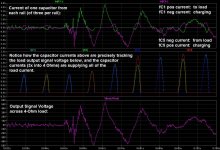
The music IS THE CAP CURRENT, almost all of the time. And the cap voltage is proportional to the integral of the cap current. So the louder the music, the bigger the ripple, and the more PSR you need. (I attached part of the intro from the song "Highway to Hell", in an LT-Spice simulation of a power amp and PSU, showing the reservoir cap currents and the output voltage across the speaker. Very enlightening.)
For all but the very high frequencies, the reservoir and decoupling (at the chip) caps are seen as one capacitance, by the chip's power pins. So maybe Peter Daniel has more capacitance near the chip amps, to make up for the crazy-low value at the PSU.
You can't just pull the capacitance value out of the air, or base it on your "opinion" of "the sound", and expect to have an amp with the max rated output power that the rail voltage would be capable of providing. Too little capacitance and the output will clip, well before the rail voltage limit. You can and should calculate the minimum acceptable capacitance, for a desired max rated power. If you then decide to use less than that, then you have to calculate the new (lower) rated max power spec.
The peak voltage of the output signal can only go up to the point where there's still room for the ripple voltage and the voltage across the amplifier itself to sit between the signal peak and the max rail voltage. Higher than that and ripple-shaped chunks get gouged out of the output signal. That's the onset of clipping. Higher still and the entire top of the output signal will get sheared off. The spray of high frequencies inherent in the sharp edges has been known to burn up tweeters, and blow the ribbon tweeter fuses of my Magnepan MG-3.6/R speakers, unless a higher-rated amp is used, so that it isn't approaching clipping at the desired (high) loudness.
We can also easily prove, mathematically, that too little capacitance means that there is a bass frequency below which the capacitors will run out of charge, before the next charging pulse comes along. The capacitance value needed, to be able to reproduce down to a particular bass frequency, also depends on the rated maximum RMS output power, which defines the peak output signal voltage and current if a sine wave is assumed.
But as abraxalito mentioned, music doesn't usually look like a sine wave (except maybe when there's a flute solo).
The most bullet-proof way to calculate the MINIMUM required capacitance is to assume that the signal could be ANY shape, and could be anywhere up to the peak output voltage and current that are implied by the rated maximum output power. To do that, we should always assume that the output signal could be constant DC, at the peak value. Then the amp will never be able to clip, ever, and will be able to handle even the lowest bass frequencies without ever running out of current.
Once you know the max rail voltage (from transformer output voltage and rectifier voltage drop at max current) and the load impedance and the "Vclip" voltage for the amplifier itself (given in LM3886 and LM3875 datasheets, as a plot versus rail voltage), then the minimum required capacitance and the max rated output power are redundant, i.e. if you have one, you can calculate the other. And if one changes, then so does the other.
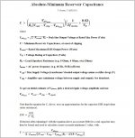
I attached the formula for calculating the absolute minimum reservoir capacitance.
But it's a whole lot easier to just let a spreadsheet calculate for you. So I attached the spreadsheet version of the formula. You can change any of the numbers in the BLUE cells, and see what happens. (Save the file with the ".txt" removed from the end of the file name.)
Cheers,
Tom
Attachments
Last edited:
You're welcome, jer.
The spreadsheet is a lot easier to use than the equation, and provides a lot more insight. It also gives the capacitance values to meet only the "DC at sine RMS value" type requirements, like most people seem to calculate for, in addition to the capacitance that will handle "DC at sine PEAK value" that the equation gives, which is how I think it should be calculated (and how it must be done, in order to be "bulletproof").
About the only difficult part, sometimes, is finding the Vclip value for the output stage, which is the voltage between the power rail and the amp output, when at the rated max output. It still amazes me that so many people forget that the voltage across the amplifier itself has to have room to sit between the top of the signal and the bottom of the ripple.
Cheers,
Tom
With the spreadsheet, after setting the specs in the top section, I typically select Data --> What If Analysis --> Goal Seek and then tell it to set each capacitance in row 21 by changing the corresponding figure in row 10.
So, for example, if I have a pile of 4700 uF caps, I will ask it to set each cap value in row 21 to a multiple of 4700, with 4700 on the far right, then 9400 to the left of that, then 14100, etc., and it automatically sets the row 10 figures and the max rated power in row 11, and any of the other rows that are affected. OR, you can manually tweak the row 10 figures, since they are blue and you are allowed to change any blue cells.
In addition to the rated max power figure, also consider the max ripple voltage. But remember that it is given for when the amp is pushing the rated max peak signal with a pathologically-worst-case DC signal, and will be much lower under most listening conditions (probably roughly 1/4th of the given value, for real music instead of DC).
Last edited:
Actually gootee - is the ltspice "highway to hell" (Oh, btw - very applicable song to the subject looking at the current peaks!) test an easily postable/sharable thing? I've read about feeding a wav to an ltspice sim but never done it...
I feel the urge to hit a sim with some pink floyd heartbeat bass, and follow up with ...zarathusta.
I feel the urge to hit a sim with some pink floyd heartbeat bass, and follow up with ...zarathusta.
Also be aware of additional decoupling capacitance requirements.
The spreadsheet only gives you the minimum capacitance value to prevent clipping and to prevent bass current starvation. The total capacitance at the PSU plus the decoupling capacitance near the point of load (near the active amplifier output stage devices) must add up to what the spreadsheet (or the equation) gives as the minimum capacitance, for your specs and your chosen rated max power.
But there are higher-frequency requirements, which only the decoupling and bypass caps can fulfill, by being very near the power connections of the output devices.
There are two separate high-frequency issues:
1. One is the hidden positive feedback loop through the power rail that affects most transistor amplifiers. For that, we must place a very small (small physical package) cap, very close to the power connection of each output device, connected between power and ground. Connection lengths of more than a few mm will make this cap much less effective. So no axial-lead caps are allowed. Use radial-lead types or surface-mount. The cap value is usually anywhere from 0.01 uF to 1 uF. The small size of the package and the use of short connections matter more than the actual capacitance value. Ceramic or film caps will work. Do not use anything worse than an X7R ceramic. NP0 and C0G ceramics, or film types, would be better. But be aware that with such low ESRs, there is a chance of high frequency LC resonances being formed with the inductance of nearby electrolytic cap(s). A very small resistance can be placed in series with the electrolytic(s), if that becomes a problem. Using an X7R bypass cap might mitigate the resonance problem. But check to see if the X7R is microphonic, by tapping on it with the volume turned up high, with no signal.
2. The other issue is the fast transient currents that will be needed. And they are not just for the frequencies in the music output, since the feedback system will also always be trying to cancel some very high frequency harmonics. It's probably safe to assume that the required transient current frequency content will extend to 300 or 400 kHz.
For those high frequencies, the tiny inductances of the traces, wires, and leads will have a significant effect. That means that all of the lengths and distances need to be very short.
The decoupling capacitance values and the maximum acceptable connection lengths and capacitor lead-spacing(s) can be calculated. Or we could use a "rule of thumb", such as
10 uF per Watt of rated max output power,
which sort-of fits with the LM3886 datasheet recommendation of 470 uF minimum, connected as close as possible to each of the chip's power pins.
-----------------------------------------------------
To try to actually calculate the minimum decoupling capacitance required, we could use the output device's maximum slew rate and maximum peak output voltage, as a worst case.
I never remember equations so let's just try to derive it from scratch:
We should know, or be able to find:
slewmax: the max slew rate in V/us,
Vpk: the max peak output voltage,
RL: the load (speaker) resistance,
dv: the maximum allowable p-p ripple voltage
The ideal capacitor equation is
i = C dv/dt
We can say
C = i dt/dv
where
i is the peak current transient
C = the required capacitance that we want to find
dt = the time it takes to reach the peak transient current
dv = the know maximum allowable peak-to-peak ripple voltage
We are assuming that the voltage slews from 0 to Vpk.
So ipk = Vpk / RL.
That ipk might be 2X what we really need to use, since it slews from 0 to ipk so the average would be 1/2 of that. But since we are going to ignore ESR of the cap, it will provide a safety margin.
dt is just
dt = Vpk / slewmax, in us (microseconds).
And we specify dv, or, rather, calculate it based on the max rated power (see spreadsheet).
So C = (Vpk/RL)(Vpk/slewmax)/dv
(Remember to divide by 1000000 for the microseconds, and then view the result as Farads. Or forget dividing by 1000000 and view the result as microfarads.)
(I must have missed something because I don't get the 470 uF that national/TI says is required for the LM3886. But you get the general idea...)
THEN we need to know how far away from the device we are allowed to place the C. The inductance of the connection lengths will decide that.
V = L di/dt, for an inductance. So we can say:
L = V dt/di
where
di = the change in current, which is our ipk, since it changes from 0 to ipk,
dt is the same as above,
V is our dv from above, so we have
L = dv(Vpk/slewmax)/(Vpk/RL)
For example, if the peak output voltage is 35V and the max slew rate is 19V/us, and we have a 4 Ohm load and the ripple needs to be 0.25 V or less, we get
L = 53 nH
If we use the typical rule of thumb for self-inductance being about 1 nH per mm, we could allow up to 53 nH "round trip", to include the conductor lengths plus the cap's lead spacing. So the C could be placed up to about 25 mm from the output device, possibly. But you should use a better estimate of the inductance of your conductors, if it's critical.
For higher-speed circuits, i.e. with faster edge times, such as digital ICs, the distance will typically be impossibly small. In that case, you would need to use multiple smaller caps in parallel, to try to divide their inductance by the number of caps.
(I have ignored the cap's ESR and the conductors' R values, everywhere above. But it gives the general idea of how it could be done.)
Actually gootee - is the ltspice "highway to hell" (Oh, btw - very applicable song to the subject looking at the current peaks!) test an easily postable/sharable thing? I've read about feeding a wav to an ltspice sim but never done it...
I feel the urge to hit a sim with some pink floyd heartbeat bass, and follow up with ...zarathusta.
aspringv,
The attached zip folder should contain four files, including a WAV file for testing the WAV input to LT-Spice.
To simplify the setup and usage of the simulation, I replaced the transformer models with ideal voltage sources.
Besides the WAV file, there is a main .ASC file, a .PLT file that automatically sets up the plotting, and the Cordell Models.txt file, which contains the spice models for the transistors used in the output stage.
Just unzip all four files into the same folder, so the ASC file can find the other three.
If you want to use a WAV file input in another schematic, you could just copy and paste the voltage source that uses the WAV file, and then change the name of the WAV file by right-clicking on it. (I think it was entered originally by just right-clicking on the displayed voltage of the source.)
Note that there is also a way to set up a WAV file to be an output, on the schematic. You could LISTEN to the output of any simulated audio circuit! Unfortunately, they don't yet simulate in real time.
I originally used the included test WAV file to simulate DC servo circuits with power amplifiers. It had to be left fairly long (40 seconds) because some of my servos had very long time constants. You might want to download some free wave file editing software, so you can create shorter snippets of the parts of WAV files that you are most interested in using in your simulations, since they run relatively slowly when WAV file data is being used or produced.
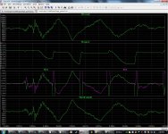
In the attached screen image of the LT-Spice simulation, you can see that it would probably be sufficient to simulate with only the portion of the WAV file between 8 and 12 seconds, or even less than that.
Looks like clipping was just barely avoided, at around 9.668 seconds, in the plot detail that I attached. You can see that the voltage across the amp (top plot pane) gets down to about 10 V, while the rail voltage has fallen to about 66.15 V, and the signal peak climbs to about 55 V, at almost the same time. (I adjusted the transformer output voltage and the reservoir capacitance, to get it close, like that.) If you want, you can also plot the input signal, so you can verify when it clips, by comparing its shape to that of the output. Or, there are ways to do waveform math to make a new "difference/error" plot, that will be near zero but will spike when clipping occurs. You can right-click on any plot heading and replace it with any math expression you like.
Cheers,
Tom
Attachments

Last edited:
- Status
- This old topic is closed. If you want to reopen this topic, contact a moderator using the "Report Post" button.
- Home
- Amplifiers
- Power Supplies
- Resevoir capacitors for Chip Amps