I also left the simulated inductances of the power and ground rails, in the simulation schematic. It's set up so that you can specify the length of the rails, in inches, and it sets the inductors' values, and their parasitic resistances, automatically, based on the parameters for those, that you can also set.
Also, the AC Mains voltage supplies are parameterized, so you just set the RMS output voltage and the frequency, by editing the existing .param statements on the schematic, and it sets the actual values for both of them.
Likewise, the capacitances and voltage ratings of the four caps per rail are all set from two param statements. And then also, their ESRs are all calculated automatically, based on the capacitance and voltage rating, using an approximate formula.
The maximum time-step should be set to 10u (10 microseconds). It could be shorter, for better accuracy. But that makes it run more slowly. You can try making it larger until something changes for the worse, in order to get the best simulation speed.
Last edited:
Tom (gootee) and abraxalito are making excellent points about important aspects ... I might just throw in now some 'extensions' to what Tom has said here - I've realised that I gave the 'wrong' advice elsewhere about what combinations of cap types are 'safe, and I will do a full rundown in my blog shortly about such,For that, we must place a very small (small physical package) cap, very close to the power connection of each output device, connected between power and ground. Connection lengths of more than a few mm will make this cap much less effective. So no axial-lead caps are allowed. Use radial-lead types or surface-mount. The cap value is usually anywhere from 0.01 uF to 1 uF. The small size of the package and the use of short connections matter more than the actual capacitance value. Ceramic or film caps will work.
 : the film or ceramic should be around 1uF, preferably on the larger value side - anything smaller is close to being useless, a mosquito bite in its impact - in the smallest physical package that neatly spans the the connection points. Then, to ensure no nasty resonance problems, and improve overall bypassing as well, have the smallest physically sized electro cap of value 100-220uF, preferably low ESR, 'bypassing' the bypass cap, . There are plenty of tiny caps like this in the catalogues, any decent quality one will do ...
Last edited:
Stripboard / Veroboard comes to the rescue here.
Most guys will agree that smaller caps improve the response of the amp. Bigger caps improve the bass.
Why not buy a nice long length of stripboard and a big bag of 1000uF Panasonics. At that value or even 470uF they are relatively cheap.
Aiming at around 10000uF, you can add caps a pair at a time to evaluate your own results.
Below 4700uF I would expect the performance to be mediocre, you can evaluate the audible gains above that for yourself.
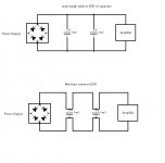
Wrong (top) and right way (bottom) to wire power supply reservoir capacitors.
The correct way is to minimise the common impedance by making sure the common point for the input and output is as close to the capacitor as possible.
Any ripple voltage generated by the extra resistance and inductance is not then transferred to the output load.
This is of the utmost importance in switched mode power supplies where large circulating currents in common PCB tracks can cause increased ripple voltage on the output. It is also applicable to 50/60Hz power supplies with high values of reservoir capacitors producing large pulses of current from the rectifier diodes due to the very short conduction times. Any common impedance noise is transferred directly to the output and onto the supply rails of the amplifier. The same applies when the amplifier takes large 'lumps' of current from the reservoir capacitor on heavy bass, the voltage drop on the supply rail is minimised.
Attachments
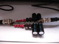
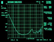
FWIW, construction and impedance plot of a capacitor strip in the above manner (4x 2200uF + 4x100uF + some films in the 47nF to 2.2uF range). As we can see, there is room for improvement at around 1MHz but it would probably do well with any chipamp.
The impedance plot is referenced to 1Ohm=0dB(+-3dB or so of uncertainity), so -40dB is 10mR. Note this is a transmisson type of measurement. If I had attached the feeding line to the output (at the film caps) to get a true 1-point impedance plot the curve would look slightly different because the resistive and inductance geometries are changed a bit. The big caps were still hot from soldering which made the plateau at 6mR possible, it went up to 10mR after cooling down.
The impedance plot is referenced to 1Ohm=0dB(+-3dB or so of uncertainity), so -40dB is 10mR. Note this is a transmisson type of measurement. If I had attached the feeding line to the output (at the film caps) to get a true 1-point impedance plot the curve would look slightly different because the resistive and inductance geometries are changed a bit. The big caps were still hot from soldering which made the plateau at 6mR possible, it went up to 10mR after cooling down.
Attachments
Last edited:
Yes, KSTR's effort demonstrates what's possible if you really want to go to town with this strategy - in the end it becomes a battle to physically locate everything to have the required impact, a 3D sculpting exercise more than anything else.
The ol' law of diminishing's climbs on board - how much low impedance do you need, to how high a frequency ...?
10mR all the way is great, 100mR much, much easier to do - that range of values is the sweet spot, worth thinking about ...
The ol' law of diminishing's climbs on board - how much low impedance do you need, to how high a frequency ...?
10mR all the way is great, 100mR much, much easier to do - that range of values is the sweet spot, worth thinking about ...
Klaus, just noted your fine work in http://www.diyaudio.com/forums/power-supplies/226070-network-analyser-measurements.html, hadn't chanced upon it earlier - nice to see theoretical and practical correlating well ...
Again, in the quest for better sound, the big 'workload' is finding out whether going to the n'th degree is useful or not, from an audible point of view. Personally, the effects of interference are such a headache to truly null that it probably makes sense pushing these sorts of performance results to at least a very high degree.
Again, in the quest for better sound, the big 'workload' is finding out whether going to the n'th degree is useful or not, from an audible point of view. Personally, the effects of interference are such a headache to truly null that it probably makes sense pushing these sorts of performance results to at least a very high degree.
"A WHOLE LOT" of PSRR is called for, when music is playing.
The music IS THE CAP CURRENT, almost all of the time. And the cap voltage is proportional to the integral of the cap current. So the louder the music, the bigger the ripple, and the more PSR you need. (I attached part of the intro from the song "Highway to Hell", in an LT-Spice simulation of a power amp and PSU, showing the reservoir cap currents and the output voltage across the speaker. Very enlightening.)
For all but the very high frequencies, the reservoir and decoupling (at the chip) caps are seen as one capacitance, by the chip's power pins. So maybe Peter Daniel has more capacitance near the chip amps, to make up for the crazy-low value at the PSU.
You can't just pull the capacitance value out of the air, or base it on your "opinion" of "the sound", and expect to have an amp with the max rated output power that the rail voltage would be capable of providing. Too little capacitance and the output will clip, well before the rail voltage limit. You can and should calculate the minimum acceptable capacitance, for a desired max rated power. If you then decide to use less than that, then you have to calculate the new (lower) rated max power spec.
The peak voltage of the output signal can only go up to the point where there's still room for the ripple voltage and the voltage across the amplifier itself to sit between the signal peak and the max rail voltage. Higher than that and ripple-shaped chunks get gouged out of the output signal. That's the onset of clipping. Higher still and the entire top of the output signal will get sheared off. The spray of high frequencies inherent in the sharp edges has been known to burn up tweeters, and blow the ribbon tweeter fuses of my Magnepan MG-3.6/R speakers, unless a higher-rated amp is used, so that it isn't approaching clipping at the desired (high) loudness.
We can also easily prove, mathematically, that too little capacitance means that there is a bass frequency below which the capacitors will run out of charge, before the next charging pulse comes along. The capacitance value needed, to be able to reproduce down to a particular bass frequency, also depends on the rated maximum RMS output power, which defines the peak output signal voltage and current if a sine wave is assumed.
But as abraxalito mentioned, music doesn't usually look like a sine wave (except maybe when there's a flute solo).
The most bullet-proof way to calculate the MINIMUM required capacitance is to assume that the signal could be ANY shape, and could be anywhere up to the peak output voltage and current that are implied by the rated maximum output power. To do that, we should always assume that the output signal could be constant DC, at the peak value. Then the amp will never be able to clip, ever, and will be able to handle even the lowest bass frequencies without ever running out of current.
Once you know the max rail voltage (from transformer output voltage and rectifier voltage drop at max current) and the load impedance and the "Vclip" voltage for the amplifier itself (given in LM3886 and LM3875 datasheets, as a plot versus rail voltage), then the minimum required capacitance and the max rated output power are redundant, i.e. if you have one, you can calculate the other. And if one changes, then so does the other.
I attached the formula for calculating the absolute minimum reservoir capacitance.
But it's a whole lot easier to just let a spreadsheet calculate for you. So I attached the spreadsheet version of the formula. You can change any of the numbers in the BLUE cells, and see what happens. (Save the file with the ".txt" removed from the end of the file name.)
Cheers,
Tom
Attached is an updated/improved version of the PSU reservoir capacitance calculator spreadsheet that I put up with post 9.
Just change the filename by removing the ".txt" from the end, so that the file name ends with ".xls".
Attachments
I've been playing around with a few LTSpice sims after Frank posted up that '10mohms all the way is great' and found that target very difficult to hit across the whole band. But its been a very interesting exercise nevertheless and revealed some of the limitations of using LTSpice in the pursuit of such demanding endeavours
First up - at the low end (say down to 40Hz) aiming for 10mohms of reactive impedance means around 400,000uF. ESRs tend to decrease quite a bit as the frequencies go down so it might be that even more is called for to get the modulus of impedance down to 10mohm.
At the top end (say 50kHz and up), there's no real substitute for SMT ceramics, fistfuls of them, paralleled up ad nauseum. My 10W chipamp has about 30 but I'm not sure this is enough. They're cheap though (10uF/25V goes for under UKP0.01 here) but they do lose a lot of capacitance under bias (10uF is down to 4uF @16V, this is brand dependent though - the poorer brands do considerably worse). For those building higher power amps (higher voltage rails than say 25V) SMT ceramics don't look such an interesting prospect though as it gets much harder to get enough uF.
In moving down from 50kHz comes the greatest challenge - how to bridge between the ultra-low impedance (30 * 10uF goes way below 1mohm ESR) of the ceramics and the brute force capacitance required at the bottom end? As Frank hints, 3D sculpting looks to be the way to go but I'm right at the earliest stages of doing this (caps on individual twisted pairs arranged in a sphere) so I'll shut up now
<edit> In Jobs style, just one more thing - the problems are ameliorated considerably if we just build lots of chipamps to parallel - 10 say can operate with 100mohm target supply impedance. Anyone tried this?
Last edited:
You are quite welcome, aspringv.
Yeah, LT-Spice is really a great aid to understanding, as long as you always try to be sure that the results are "reasonable", and also are not "too good to be true" because of some built-in ideal-ness or unrealistically-perfect symmetry, or whatever. (But it does make me wish that my computer was at least 100X faster.)
I love being able to click anywhere and plot any voltage or current, and even power dissipation of absolutely any component OR subsystem (Alt-Left-Click). And I love being able to integrate any portion of any plot so easily (and get the average and RMS values), or see its FFT.
The .step operator is also extremely powerful and helpful, providing the ability to do multiple nested sweeps of parameters, automatically running a whole simulation for each case, and putting all of the plots in one plot pane when it's all done.
It's pretty easy to make your own components and sub-circuits, too. I have a couple of simulation schematics that look more like a block diagram or flow chart. I have entire circuits in each box, with their inputs and outputs defined, and I can just connect the boxes together and run it. Right-clicking on a box gives access to the schematic. And you can have as many sub-levels as you want.
I could go on and on. And the fact that it's free and still constantly being developed is almost too good to be true. The discussion group at yahoogroups is also truly excellent.
Last edited:
Having fun, Richard ...?
I don't know what the precise answers are, so it's definitely worthwhile for you, Richard, to persevere and get more answers - to add to the pool of greater knowledge, for all to benefit ...
Cheers,
I 'cheat' here ... use regulators to get the job done - to me, this is the smarter way to go ...First up - at the low end (say down to 40Hz) aiming for 10mohms of reactive impedance means around 400,000uF. ESRs tend to decrease quite a bit as the frequencies go down so it might be that even more is called for to get the modulus of impedance down to 10mohm.
As always, the Law of Diminishing Returns will get you - there has to be a 'sweet spot' of just enough low ESR at the right frequencies for the amplifier in a particular situation to work at, say, 98% of its best. And if that's good enough for the sound out to be 'right', then how much effort does one want to expend, to eke out just that little bit more?In moving down from 50kHz comes the greatest challenge - how to bridge between the ultra-low impedance (30 * 10uF goes way below 1mohm ESR) of the ceramics and the brute force capacitance required at the bottom end? As Frank hints, 3D sculpting looks to be the way to go but I'm right at the earliest stages of doing this (caps on individual twisted pairs arranged in a sphere) so I'll shut up now
I don't know what the precise answers are, so it's definitely worthwhile for you, Richard, to persevere and get more answers - to add to the pool of greater knowledge, for all to benefit ...
Cheers,
Last edited:
I've been playing around with a few LTSpice sims after Frank posted up that '10mohms all the way is great' and found that target very difficult to hit across the whole band. But its been a very interesting exercise nevertheless and revealed some of the limitations of using LTSpice in the pursuit of such demanding endeavours
First up - at the low end (say down to 40Hz) aiming for 10mohms of reactive impedance means around 400,000uF. ESRs tend to decrease quite a bit as the frequencies go down so it might be that even more is called for to get the modulus of impedance down to 10mohm.
At the top end (say 50kHz and up), there's no real substitute for SMT ceramics, fistfuls of them, paralleled up ad nauseum. My 10W chipamp has about 30 but I'm not sure this is enough. They're cheap though (10uF/25V goes for under UKP0.01 here) but they do lose a lot of capacitance under bias (10uF is down to 4uF @16V, this is brand dependent though - the poorer brands do considerably worse). For those building higher power amps (higher voltage rails than say 25V) SMT ceramics don't look such an interesting prospect though as it gets much harder to get enough uF.
In moving down from 50kHz comes the greatest challenge - how to bridge between the ultra-low impedance (30 * 10uF goes way below 1mohm ESR) of the ceramics and the brute force capacitance required at the bottom end? As Frank hints, 3D sculpting looks to be the way to go but I'm right at the earliest stages of doing this (caps on individual twisted pairs arranged in a sphere) so I'll shut up now
<edit> In Jobs style, just one more thing - the problems are ameliorated considerably if we just build lots of chipamps to parallel - 10 say can operate with 100mohm target supply impedance. Anyone tried this?
I suggest that you go to the Cornell Dubilier website and use their Java applet. It automatically produces FREQUENCY-DEPENDENT spice models for their electrolytic caps (and the models are temperature-dependent, as well).
Also look at the plots the applet gives, for ESR and capacitance versus frequency and temperature, with variable inductance.
Yeah, the 3-D "arrays" of paralleled caps interested me, too. I haven't played with it much, yet. Large unbroken copper planes work well, too, in certain regimes (see posts by Terry Given). The problem always comes down to the inductance of the connections, it seems. And at the end, you still have to be able to connect them at the point of load, without connections that wreck the fruits of your labor. (Maybe consider 2-sided PCBs in 3-D shapes, full of caps?)
Yes, that reminds me, I did a lot of simulations of paralleled chip amps. Back then, the only halfway-decent spice model, for a chip amp, was the OPA541E. At least it also modeled the supply pin behavior, and seemed pretty good, otherwise, too (modeling-wise). I usually had the paralleled chip amps in the forward path of an op amp's feedback loop, inside the loop, just after the opamp output, more or less. That topology seemed capable of providing some "baked-in goodness" that I couldn't easily get otherwise. It also turned out to be the answer for driving highly-capacitive loads: excess current-dumping capability (with the right feedback compensation, etc, for the op amp, of course). Just make sure you have a low-pass filter on the overall input, limiting the slew rate to 7 V/us, or whatever the max is for the chip amps you use. It was lovely to see how smart the outer feedback loop could seem. For example, for a square wave signal, the input to the chip amps would contain a spike, to jumpstart the rise time, and then another one the opposite way to make it instantly stop rising, to turn a perfect corner and become the flat top of the square wave (and similarly for the falling edge). It had WAY better transient response than just trying to put the original square wave signal directly into the chip-amp inputs.
Last edited:
Agree. To get decent feedback, in a decent timeframe, one needs to learn to play with the various settings, not be scared of doing 'rough' sweeps to get quick indications of where interesting things may be happening ... and then 'zooming' in with finer resolution of the simulation engine in the key areas ...Yeah, LT-Spice is really a great aid to understanding, as long as you always try to be sure that the results are "reasonable", and also are not "too good to be true" because of some built-in ideal-ness or unrealistically-perfect symmetry, or whatever. (But it does make me wish that my computer was at least 100X faster.)
That's what you think! The curse of Twitter and Facebook has struck, and there's a new interface which is bloody awful!! Hopefully, somebody will get sensible, and move the discussion group to another site which is not such a mess ...The discussion group at yahoogroups is also truly excellent.
Having fun, Richard ...?
Most certainly! This stuff really is fascinating me, hard to say why.....
I 'cheat' here ... use regulators to get the job done - to me, this is the smarter way to go ...
Yes I adopted an LM338 reg on my chipamp but still I got improvement in SQ by adding on more caps. Not only that but the PSU noise as recorded reduced too. If the reg was doing the heavy lifting already, why would this happen? Admittedly I'm not at the 400,000uF level yet, I gave up at 140,000uF as I figured the amp was becoming too unstable (physically, not electrically).
Yep, agree its all about finding a particular local optimum, not taking everything to extremes..... Some extremes are really fun though aren't they in terms of understanding what's really important to the SQ.
As an aside to this, I was earlier this week searching on Taobao for caps and noticed there are a lot of choices of very high voltage lytics (400V-450V). When I did the math I found such caps have considerably better energy storage per unit volume than the caps used for chipamps (say 35V working voltage and below). Its something like a 4X improvement. Anyone else noticed this? Transformers came to mind next....
Feedback is something that one 'needs' to develop an intuition for, as to how it "really works". As you say, it's 'clever' enough to compensate for the amp's "lack of performance" - which is what it's all about ...It was lovely to see how smart the outer feedback loop could seem. For example, for a square wave signal, the input to the chip amps would contain a spike, to jumpstart the rise time, and then another one the opposite way to make it instantly stop rising, to turn a perfect corner and become the flat top of the square wave (and similarly for the falling edge). It had WAY better transient response than just trying to put the original square wave signal directly into the chip-amp inputs.
Interesting ... there are some subtleties happening there, interactions which are not obvious, because of layout, stray parasitics, qualities of the components - it's a fine dance indeed ...Yes I adopted an LM338 reg on my chipamp but still I got improvement in SQ by adding on more caps. Not only that but the PSU noise as recorded reduced too. If the reg was doing the heavy lifting already, why would this happen?
The thirst for understanding certainly plays a part, and is all good ...Some extremes are really fun though aren't they in terms of understanding what's really important to the SQ.
As an aside to this, I was earlier this week searching on Taobao for caps and noticed there are a lot of choices of very high voltage lytics (400V-450V). When I did the math I found such caps have considerably better energy storage per unit volume than the caps used for chipamps (say 35V working voltage and below). Its something like a 4X improvement. Anyone else noticed this? Transformers came to mind next....
There are certainly "sweet spots" for capacitors, depending upon precisely how they're made. At one stage I spent weeks going through the catalogues, comparing and contrasting the offerings from all the companies, to get a sense of precisely which capacitor, from which company, for the money, was optimum ...
Yes there are sweetspots for caps - I also trawled various datasheets looking for support for hypotheses like '35V has the lowest ESR'. Sweetspots though are spots, by definition. Here in looking at high voltage caps though, its a whole vast prairie of sweetness, just there aren't any chipamps with 450V supply ratings to leverage it....
- Status
- This old topic is closed. If you want to reopen this topic, contact a moderator using the "Report Post" button.
- Home
- Amplifiers
- Power Supplies
- Resevoir capacitors for Chip Amps