Hello!
I am new in this forum and I have not electronic skills.
But I am very very handy with an iron...
I am in a Naksa80 project, but I have a Gaincard without psu. It was one of my amps in the past.
Well, I know there is a lot of criticism about the gaincard, but it doesn't matter for me. I LIKE IT! May be there are some gainclones that sound much better than the gaincard. But I love the gaincard and I will not put it in the garbage - I know that many Diyers will throw it away.
I just want a few answers, simple things.
So I am asking your help. I know that I am not known here and I don't know anybody here. I just want a litle of your knowledge. Please.
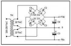
Here is what I have, a schematic of the gaincard psu and a list of components:

Diode de redressement ultra rapide STTA1206D - Diodes, ponts (two)
Diode de redressement ultra rapide RHRP 1560 - Diodes, ponts (two)
Condensateur électrochimique polarisé radial -2200µF - 35V - Condensateurs polarisés (two)
Transformer
Transformateur R-CORE à fixation sur châssis 300VA - 2 x 24V - Transformateurs électriques (two)
Obviously, my intention is to make a double mono psu.
First question :
Can I use a 300VA - 30V x 2 R-core ? (What is suggested is one with 24 volts secondaries) If yes, should I use the same components as suggested above?
Why 30V? Because I have two of these R-cores...
Thank you very much.
I am new in this forum and I have not electronic skills.
But I am very very handy with an iron...
I am in a Naksa80 project, but I have a Gaincard without psu. It was one of my amps in the past.
Well, I know there is a lot of criticism about the gaincard, but it doesn't matter for me. I LIKE IT! May be there are some gainclones that sound much better than the gaincard. But I love the gaincard and I will not put it in the garbage - I know that many Diyers will throw it away.
I just want a few answers, simple things.
So I am asking your help. I know that I am not known here and I don't know anybody here. I just want a litle of your knowledge. Please.
Here is what I have, a schematic of the gaincard psu and a list of components:
Diode de redressement ultra rapide STTA1206D - Diodes, ponts (two)
Diode de redressement ultra rapide RHRP 1560 - Diodes, ponts (two)
Condensateur électrochimique polarisé radial -2200µF - 35V - Condensateurs polarisés (two)
Transformer
Transformateur R-CORE à fixation sur châssis 300VA - 2 x 24V - Transformateurs électriques (two)
Obviously, my intention is to make a double mono psu.
First question :
Can I use a 300VA - 30V x 2 R-core ? (What is suggested is one with 24 volts secondaries) If yes, should I use the same components as suggested above?
Why 30V? Because I have two of these R-cores...
Thank you very much.
The maximum voltage from your transformer is
Vout ~ Vmains/Rated mains voltage * Transformer regulation+1 * sqrt(2).
If your transformer is a 230:30Vac and 7% regulation then Vout max ~ 234 /230 * 0.07+1 *1.414 ~ 46.2Vpk
The maximum DC after a rectifier can be ~ 45.7Vdc. Far too high for a 35Vdc capacitor. Use 50V capacitor or higher.
In the UK that 234 becomes 254 for ~49.6Vdc.
The right components
Thank you dfy and AndrewT!
I just saw your replys now, I thought that I would receive an email notification, but not in this forum. Anyway, I was a litle disappointed with no answers, and I decided to take a look and for my surprise, I had two nice answers. Is there a feature in this forum that I can use to receive automatic notifications?
Well, I live in France, so your calculations are right.
So : If I buy the same kind of capacitor, BUT with at least 50V and the same diodes, can I make this psu for my gaincard?
Is it the same in terms of sound quality? (Sorry for my ignorance).
I am planing to use only one transformer for the moment, because I will use the other to another project, wich is a NAKSA80 that requires 30V secondaries.
TO MAKE IT SIMPLE :
What components should I buy to complete my psu? (with this transformer, of course).
Finally, I think that 47LABS don't use capacitors in the gaincard psu. If it is true, i'd like to exclude the capacitors. What components should I buy then?
Thank you very much for taking the time to help me.
DON'T exclude the reservoir capacitors. If anything, use more than you planned, rather than less. It would be much better to use three or four 4700 uF for each power rail.
But you SHOULD exclude the capacitors that are across the rectifier diodes. That is a bad design. If you want to keep them, then you will need a small resistor in series with each one. But then it would be better to place a cap with a series resistor across each secondary, instead of having any across the diodes.
But you SHOULD exclude the capacitors that are across the rectifier diodes. That is a bad design. If you want to keep them, then you will need a small resistor in series with each one. But then it would be better to place a cap with a series resistor across each secondary, instead of having any across the diodes.
Last edited:
Hi gootee, thanks!
This could be a good choice, right?
Mundorf M-Lytic AG - Condensateur Mundorf M-Lytic AG 63V 3300µF
Can anyone make a simple design explaining how I should make this power supply? I mean a representation of the components and their values, like a design for a kid.
Thanks for all the support.
This could be a good choice, right?
Mundorf M-Lytic AG - Condensateur Mundorf M-Lytic AG 63V 3300µF
Can anyone make a simple design explaining how I should make this power supply? I mean a representation of the components and their values, like a design for a kid.
Thanks for all the support.
(Just FYI, most knowledgeable people think that the 47 Labs gaincard was not a good design, except for making money.)
With an LM3875, with 44.5-Volts for the power rail, 3300 uF would give you a max rated output power of about 48 Watts (at clipping start), and about 24% ripple (10.8 V p-p).
The 3875 would have a Vclip of about 6 Volts, with a 44.5-Volt rail voltage. So your peak output voltage would be Voutpk = Vrail - Vclip - Vripple = about 27.7 Volts.
BUT, the "absolute maximum" supply voltage, for an LM3875, is +/-42 Volts, according to the official datasheet.
So your transformer voltage is too high, for an LM3875. You could lower it, either with a regulator after the capacitor, or maybe with four diodes in series before the capacitor.
The LM3886 has the same maximum supply voltage limit.
I understand gootee. Finally, I think that is preferable to buy another transformer to the gaincard, (or two), with 24 volts secondaries, if I want to keep this amp. So, I'll use the components refered above :
Diode de redressement ultra rapide STTA1206D - Diodes, ponts (two)
Diode de redressement ultra rapide RHRP 1560 - Diodes, ponts (two)
Condensateur électrochimique polarisé radial -2200µF - 35V - Condensateurs polarisés (two)
Transformer
Transformateur R-CORE à fixation sur châssis 300VA - 2 x 24V - Transformateurs électriques (two)
You say that
..."most knowledgeable people think that the 47 Labs gaincard was not a good design, except for making money".
May be you're right, all I know is that I had many amps before and I have the Essence loudspeakers from 47Labs, (or Konus Audio), and I really like the Gaincard with the Essence.
May be what we have here is a very bad design that sounds very good... at least for me.
Well, I will keep both transformers to another project, wich is the Naksa80, that demands 30v for secondaries, exactly what these transfos have.
Now, the question is : Wouldn't it be better to make the LM3875 kit from audiosector? It would cost more or less the same! I'm tempted...
Gaincard for sale!
Thanks for your help, it was not for nothing.
Diode de redressement ultra rapide STTA1206D - Diodes, ponts (two)
Diode de redressement ultra rapide RHRP 1560 - Diodes, ponts (two)
Condensateur électrochimique polarisé radial -2200µF - 35V - Condensateurs polarisés (two)
Transformer
Transformateur R-CORE à fixation sur châssis 300VA - 2 x 24V - Transformateurs électriques (two)
You say that
..."most knowledgeable people think that the 47 Labs gaincard was not a good design, except for making money".
May be you're right, all I know is that I had many amps before and I have the Essence loudspeakers from 47Labs, (or Konus Audio), and I really like the Gaincard with the Essence.
May be what we have here is a very bad design that sounds very good...
at least for me.Well, I will keep both transformers to another project, wich is the Naksa80, that demands 30v for secondaries, exactly what these transfos have.
Now, the question is : Wouldn't it be better to make the LM3875 kit from audiosector? It would cost more or less the same!
I'm tempted...Gaincard for sale!
Thanks for your help, it was not for nothing.
why small psu cap?
I never understand why smaller PSU cap can lead to better sound? More ripple under load is for sure, that is physics. But nobody actually claim more ripple leads to better sound.
3000uF has less impedance than 10000uF at 20kHz, that I know form cap specs. If impedance is the reason, why not put a 300uF,which has lowest impedance at 20Khz, in paralelle with 20000uF cap, for the price I do not see the cap cost is a reason here, at least not for 47 lab amplifier.
But you SHOULD exclude the capacitors that are across the rectifier diodes. That is a bad design. If you want to keep them, then you will need a small resistor in series with each one. But then it would be better to place a cap with a series resistor across each secondary, instead of having any across the diodes.
I'm just starting with circuits and I'm curious as to why this is a poor design choice? Does it let a little AC go the "wrong" way around the diodes?
When the diodes turn off, their capacitance and the transformer leakage inductance ( and any other stray L and C that are around) form an LC resonance at some high frequency, and often a spike or ringing occurs.
The best mitigation for that is a snubber resistor that is tuned to the characteristic impedance of the LC circuit.
A capacitor is usually needed, in series with the resistor, so that only the unwanted high frequencies can pass through the resistor, so that less power is wasted and so that the resistor can be have a lower power rating. And that's the only reason for the capacitor, which should usually be 4x to 10x the value of the parasitic capacitance part of the LC.
The snubber can be placed across the transformer secondary, or, one can be placed across each diode.
Either way, using only a capacitor misses the point. Without the resistor, there is nothing to dissipate the power in the high-frequency spike and/or ringing. So the unwanted stuff is not removed. With capacitors only, all that happens is that the unwanted LC resonance is shifted to a lower frequency.
I like putting a single snubber network across the secondary, because that also seems better at preventing any high-frequency spikes and ringing from appearing on the AC Mains wiring.
Cheers,
Tom
Last edited:
I never understand why smaller PSU cap can lead to better sound? More ripple under load is for sure, that is physics. But nobody actually claim more ripple leads to better sound.
3000uF has less impedance than 10000uF at 20kHz, that I know form cap specs. If impedance is the reason, why not put a 300uF,which has lowest impedance at 20Khz, in paralelle with 20000uF cap, for the price I do not see the cap cost is a reason here, at least not for 47 lab amplifier.
Sorry. No.
A smaller PSU reservoir capacitance would not typically lead to better sound. So you are correct about that.
But LOWER impedance is BETTER, for PSU caps.
And a 3000uF cap has much MORE impedance than 10000 uF, at any frequency.
For one thing, the magnitude of the capacitive part of a cap's impedance is
|Zcap| = 1 / jωC
So a smaller C means a larger capacitive impedance magnitude.
And the ESR (equivalent series resistance) is also smaller, for larger-valued electrolytic caps. It is roughly
ESR = 0.02 / (C x Vrating)
So again, a smaller C means a larger ESR portion of an electrolytic cap's impedance.
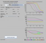
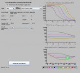
The Cornell Dubilier website has a capacitor impedance applet, which also automatically creates frequency and temperature dependent spice models, for their caps. Below are the impedance plots for a 3300uF 25V cap and a 10000 uF 25 V cap. As expected, the impedance at 20 kHz is about 3X higher for the smaller cap.
Attachments
Hi!
As I told before in this threat, I decided to buy the LM3875 Kit from Audiosector.
The suggested tranfos must have 22volts sec's.
I found some transformers with 300 VA with 25x2 Secondaries by a very good price.
Is it safe to use them with the LLM3875?
Thanks!
As I told before in this threat, I decided to buy the LM3875 Kit from Audiosector.
The suggested tranfos must have 22volts sec's.
I found some transformers with 300 VA with 25x2 Secondaries by a very good price.
Is it safe to use them with the LLM3875?
Thanks!
Hi!
I just received a Premium Kit (HERE), with the Caddock resistors.
I am building it without any electronic skills, but I'll get there.
I would like to know where should I install those Caddocks!
(No problem with the nfeedback resistor, it must be soldered in the litle hole near the LM3875 and on the second leg of it...right?)
There are two remaining Caddocks : one 22K and one 220R. (See here in discription LM378 Premium Kit)
Where should I solder these ones? I have holes for Rf, R2, R1 R3 and Rz.
(I think I will ignore Rz...)
Please don't laugh but... these resistors are not directional, are they?
Second question : Where do I solder the 680R 0.5w Riken resistor?
Thank you!
Last edited:
- Status
- This old topic is closed. If you want to reopen this topic, contact a moderator using the "Report Post" button.
- Home
- Amplifiers
- Power Supplies
- PSU for Gaincard - Questions