Hi
I have a TC Electronics G-Major guitar effects processor with a failed power supply. It seems this is a common issue and was wondering if any diyAudio members have had any similar experiences and resolved them with a diy fix.
The manufacturers refer to local suppliers who have a 300%mark up on a replacement psu and I am wondering if it is worth the time and effort trouble shooting the psu and fixing if it is repairable.
Any advice or direction is appreciated.
Thanks
Hi Thump LUMP
Thanks for positive the response.
I have no access to service manuals or schematics for the PSU. But the following information is printed on the PSU pcb.
1)The Board is JKS020Q1 Rev: D.
2)Connections from PSU to PCB indicate
that the Primary voltage is for Australian use (230v)
secondary voltages are: +3V, +5v as well as +15V 0v -15V.
Hope this information helps. I will upload some images of the PSU this evening.
There are known issues with both power supplies. If you let me have the model number of the Soundcraft, I may be able to help. As for the G Major, it is discontinued but the issues should be easily resolved as long as the board is OK.
Soundcraft suffer from regulator issues.
Soundcraft suffer from regulator issues.
Thanks for the encouraging comment but I am not sure of what you mean re:
...both power supplies? are there two psus in the G-Major?
the numbers I provided :The Board is JKS020Q1 Rev: D. were off the psu board close to the Mains power connector. I will upload pics later this evening.
...both power supplies? are there two psus in the G-Major?
the numbers I provided :The Board is JKS020Q1 Rev: D. were off the psu board close to the Mains power connector. I will upload pics later this evening.
I would check to see if it is dead or just tripping,
If dead, change the FET and blue capacitor next to it and check the resistor values in the primary side. BE CAREFUL as the main smoother may have 300volts on it!
If tripping check for short circuit secondary diodes and leaking secondary electrolytic capacitors. A shorted diode will cause it to trip.
In that case, as you are not too sure, be very careful and first thing is to discharge the main capacitor the blue electrolytic next to the transformer.
When you are satisfied that it is safe to remove the board to allow access to the copper side, release the board to allow access to the copper side.
Check the secondary diodes for short circuits. If all OK, replace the FET power transistor and the blue small capacitor between the FET and transformer. Check the value of the resistors on the FET side. That is about it. Any more will require an isolating transformer and test gear with a lot of knowledge.
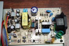
component locations
Thanks. I am aware of the cap risks and will discharge them. The psu has been standing in the G-Major dismantled for over a month now so it should be safe, but I will still discharge them to be on the safe side.
I have attached pic of the psu with components of interest marked:
- FET is attached to heatsink.
-Blue capacitor of interest
-four resistors -two north of blue cap and two south of blue cap.
Are these the focus of troubleshooting?
The diodes you mention are those the zener diodes along the bottom edge of the pcb?
Attachments
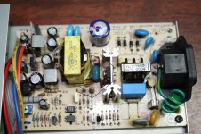
The components circled are the primary suspects. The diodes are the components with heat sinks on them and the transistor looking device. All west of the transformer.
I suppose it could be said that if you change all of the components it is bound to work again.
An new ATX computer power supply has +3 +5 +12 -12 and may be a way to go if you are unsuccessful.
I suppose it could be said that if you change all of the components it is bound to work again.
An new ATX computer power supply has +3 +5 +12 -12 and may be a way to go if you are unsuccessful.
The problem with being on the other side of the world is that you don't see things for hours later. 
The G Major has a SMPS which is exactly what I am getting away from with my thread on here pertaining to my Soundcraft. It has now been sorted and I won't be going back to a SMPS in favor of a linear supply.
Sorry but the SMPS in the G Major is over my head.
The G Major has a SMPS which is exactly what I am getting away from with my thread on here pertaining to my Soundcraft. It has now been sorted and I won't be going back to a SMPS in favor of a linear supply.
Sorry but the SMPS in the G Major is over my head.
I removed the psu from the unit and checked the following components with DVM:
Diode D11 (SB 3400141 test reading 0.14 one way, with probes switched OL
Resistors: R2 = OL both ways
R7=481.5 Ohms
Diodes D5= OL both ways
D9=0.04 in both directions
ZD1=0.644 one way only
D8=1.234 one way 0.5733 with probes switched
D7=1.225 one way and 0.572 with probes switched
I have removed R2 to find the values for the band codes Brown, Green, Yellow Gold.
Schematic!!
Hi everyone, hope some folk are still interested in this thread as I just bought a T.C. M-One reverb unit which has the same power supply you guys are talking about for the G-Major (by some stroke of luck it's the same model and revision number and everything!). I bought the unit knowing that it was faulty to try to repair it, the previous owner said that one day it just wouldn't power up. Strangely enough, when I took delivery of it it actually powered up fine, but later that day it just refused to work...
Only just started trying to diagnose the fault, so far I've found that none of the PSU outputs are supplying any voltage to the processing board.
I did manage to come across the circuit diagram for the PSU on-line:
http://www.dirk-hendrik.com/temp/TC_electronic_SMPS%20JKS020Q1.pdf
It looks to me like the unit uses the 3.3 Volt line to regulate the switching of the chopper transformer via a feedback loop (top of the diagram / Q1 & Q2 switching circuits), all the other lines are just linear voltage regulators off of the other secondary taps.
Interestingly enough, I found this thread about the XL version of my reverb unit, different symptoms but read post #11:
TC Electronic M One XL? - Gearslutz.com
My meter is reading about 46 Ohms in both directions over that component, which doesn't seem quite right for a capacitor! I'd expect it to look like a short at first then read open circuit after a short length of time.
Don't know if that's the fault or not, or if it's one of several faults, anyone else want to comment?
Cheers!
Update:
I was metering the bottom of the PSU's PCB between the -ve side of C10 and one of the transformer's primary pins (the one connected to the Drain of Q2) and all of a sudden my unit booted up! The red LED on the processing board is flickering a bit, but I'm going to stick some audio through it!! Seems to be a case of removing the power makes the PSU need that kick start again, but maybe it's a clue to what's wrong with it in the first place....
I was metering the bottom of the PSU's PCB between the -ve side of C10 and one of the transformer's primary pins (the one connected to the Drain of Q2) and all of a sudden my unit booted up! The red LED on the processing board is flickering a bit, but I'm going to stick some audio through it!! Seems to be a case of removing the power makes the PSU need that kick start again, but maybe it's a clue to what's wrong with it in the first place....
- Home
- Amplifiers
- Power Supplies
- TC Electronics G-Major Power supply failure