I am looking to build a custom PCB for a THAT 1206 line receiver but need a regulator to supply power to the device. I've been reading through a lot of the regulator threads recently and have encountered a wealth of information. Sadly I'm not knowledgeable or skilled enough yet to take advantage of all that I have read.
I considered trying the Jung circuit as well as say the LT3032. I don't think I have seen a post stating there is a idle current sweet spot for the Jung circuit or if this would be based on parts selected, circuit topology, etc...
I was considering the LT3032 mostly due to simplicity as it provides a positive and negative reg in one IC.
I'm to deliver +/- 15v DC to the THAT 1206.
Any help or direction is greatly appreciated. Feel free to refer me to further reading if you think that the best method for me to arrive at a conclusion and suitable regulator.

breaking things
I will take a look at the datasheets for 7815 / 7915 regulators.
and I think a lot of the time you are correct, if you don't understand something don't mess with it. However by breaking things often leads to quality learning opportunities...at the expense of a time and frustration
-TJ
I will take a look at the datasheets for 7815 / 7915 regulators.
and I think a lot of the time you are correct, if you don't understand something don't mess with it. However by breaking things often leads to quality learning opportunities...at the expense of a time and frustration
-TJ
Regulator performance for low current applications
Gajanan,
I believe while reading through John Bau's thread on this forum I saw that he discovered some fairly bad non-linear behavior in the 317/337 in the absence of enough idle current.
Otherwise I would be inclined to simply use the setup and values he obtained through his extensive testing.
I will admit I can't remember now what was non-linear, perhaps not in terms of noise but in terms of impedance or phase as that was the work John was doing I believe.
I'm really kinda wondering what the measured behavior is for a Jung style regulator with such a low idle current.
Anyone have an opinion on the LT3032...it looks quite nice though expensive. I really wish I could afford all the nifty test gear to answer a lot of these questions. Then again I really wish I knew how to use and analyze the results of all the fancy test gear.
I work for a router manufacturer and I'm sure I could get access to all sorts of high end equipment though I'd need someone to give me very detailed guidance on what and how to measure.
-TJ
One approach would be to use John Bau's final LM337/LT1085 circuit, and then connect a 330 ohm, 2 watt resistor from regulated +15V to ground, and another 330 ohm, 2 watt resistor from regulated -15V to ground. Presto, now you're delivering 7-8 mA to the load (THAT 1206), and delivering another 45 mA to each of these 330 ohm resistors. The regulator ICs each have a load current of 53 mA, so John Bau's min-current criterion is met.
But of course this requires an unregulated power supply which can deliver such a gigantic amount of power (15V x 53mA x 2 rails = 1.6 watts). If you're using batteries as the unregulated power supply, it may not be feasible. If you're using a mains transformer + rectifiers + filter capacitors, it will probably be easy.
Another approach would be to implement a constant current source + shunt regulator for each rail. Set the constant current source for something greater than 8 mA, and set the shunt for 15 volts. Done. The lower you set the CCS, the less power you "waste" in the regulator. This gives you, the designer, a trade-off knob that you can adjust and twirl however you wish: Battery life vs. line_regulation & load_regulation.
One PCB
All thanks very much for the very useful suggestions. transistormarkj I was wondering if it would be feasible to use resistors to draw the necessary current to put the regulators in their most comfy current range.
Indeed the THAT 1206 does have excellent PSRR, however one nice thing about DIY is you get to implement over the top designs if you so choose so while I might not be able to hear the difference, I would be able to sleep at night
I was considering the use of the Salas shut reg, not sure how it does with low current draw and I guess I should pile a few more ... well lets not say requirements but nice to haves into this topic.
I'd like to keep the PCB as small as possible and still achieve excellent regulator performance. I intend to implement the THAT 1206 + power supply on one PCB. So this means using SMD components. This is why I was considering the LT3032 but I guess there aren't many folks how have experience with that part.
I will write a bit more about my intended application a bit later and perhaps mock up a PCB based on transistormarkj suggestion.
Again thanks everyone for the responses.
You could use four of the size 1210 SMD resistors (0.5 watt rating) to get a 330 ohm, 2 watt resistor in SMD. (330R parallel 330R) series (330R parallel 330R) for example.
Four of the size 0805 resistors (0.4 watts) will get you 330 ohms, 1.6 watts. Since you're actually dissipating (15.0 x 0.046) = 0.682 watts, you might deem this margin of safety to be "adequate."
LT1085 and LM337 are available in SMD, and so are the excellent rectifier diodes MURS120T and ISL9R860S.
LT1963A/LT3015
Jackinnj,
I'm guessing the combo you mention would be superior to LT3032 due to the faster transient response? As I don't believe the noise figure is as good. It looks as though these puppies have a lot more current capability than I'd need.
As for the application of all of this. I've built 5 Randy Slone Totem Pole amps for my home theater and have been having a tough time eliminating all the grounding hummm...
I've got it to a point where its not audible while sitting on my couch...but putting the ear to the speaker I can still hear it and its bugging me. So figured by going to a grounded connection to my Marantz 8801 may help a tad.
Better use 317L/337L
Gajanan Phadte
The idle current issue u mentioned at post#5 is for the 317T and the one I mentioned are low current versions with L suffix which supply 150mA current instead of the 1.5A for the T version. Just to clarify
Anyhow, a shunt regulator is preferred over these.
Gajanan Phadte
Jackinnj,
I'm guessing the combo you mention would be superior to LT3032 due to the faster transient response?
They surprised everyone by how well they performed in the great regulator bakeoff.
One of the best regulators for transient response is the Belleson -- but it's sound quality was assessed as "middling".
Noise was the least correlated factor when judging sound quality.
Walt Jung advocates modifying his "Jung Super Regulator" to a shunt topology (link to audioXpress interview), schematic on page 6.Any suggested shunt circuits out there other than the Salas?
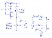
Me, I'd probably start with something plain and simple like the attached. (Negative regulator would be the mirror image, more or less). You may decide to replace the single LED with a series string of several LEDs, to meet Walt's guaranteed start-up criteria: voltage dropped across string is larger than the reference voltage across IC1.
I've suggested puny transistors with low max-power specs, for this application whose load current (6 - 7 mA) is known to be low. Higher output current would need beefier transistors.
Attachments
Last edited:
- Status
- This old topic is closed. If you want to reopen this topic, contact a moderator using the "Report Post" button.
- Home
- Amplifiers
- Power Supplies
- Good Regulator for 7 - 8ma load