Hello good afternoon
Participate in the forum ah some time however, I read enough posts and learn a lot
Now I need some help, I'm trying to adjust a current of 0 to 50A with TL 494! would be possible? if so would like to know how to calculate this current setting to put in a half-bridge SMPS that I'm developing.
already researched on various websites however not clear how to perform this calculation.
any help will be welcome
since already appreciate the help.")
Participate in the forum ah some time however, I read enough posts and learn a lot
Now I need some help, I'm trying to adjust a current of 0 to 50A with TL 494! would be possible? if so would like to know how to calculate this current setting to put in a half-bridge SMPS that I'm developing.
already researched on various websites however not clear how to perform this calculation.
any help will be welcome
since already appreciate the help.
Last edited:
Break down your requirements.
What feedback signal does the 494 need to regulate to?
How are you measuring your 0-50A?
What circuitry do you need to get the measurement of 0-50A to the feedback point of the 494?
We (anyone) needs more information.
Otherwise our suggestions will meet with: "I can't do it that way because..."
What are you starting with and what do you need exactly?
I made changes to an ATX power supply, now I want to regulate the amperage her
I got this stuff on tl 494, however I do not know sure how to calculate this current control!
TL494 Smps Kontrol Entegresi Hakk?nda | Elektronik Devreler Projeler 320 Volt
Would you like help from experts SMPS!
thank you
Heidern
I got this stuff on tl 494, however I do not know sure how to calculate this current control!
TL494 Smps Kontrol Entegresi Hakk?nda | Elektronik Devreler Projeler 320 Volt
Would you like help from experts SMPS!
thank you
Heidern
Break down your requirements.
What feedback signal does the 494 need to regulate to?
How are you measuring your 0-50A?
What circuitry do you need to get the measurement of 0-50A to the feedback point of the 494?
We (anyone) needs more information.
Otherwise our suggestions will meet with: "I can't do it that way because..."
What are you starting with and what do you need exactly?
hi im busy developing a inductor tes fixture circuit around a TL 494 the new version will have current sense control.. when you say you want current limiting then i assume you want the system to shut down if it reaches the pre-defined user threshold max = 50A
The TL 494 has 2 error amps, a dead-time control DT pin and a feedback pin, any of these can be configured to do what you need depending how you configure it. I think the IC can work in both in voltage and current mode.
In my application im using the one error amp as a current sense (wired up as a comparator with a reference and a sample taken from a 0.047ohm shunt) if the current exceeds the threshold it shuts down the chip. the other error amplifier is wired as a comparator as well only this time i use it to monitor the temperature on the heat-sink and will shut-down ic if the temperature exceeds a pre defined temperature.
my sample current is taken from a 5watt 0.047 shunt to detect up to 10amps.. and using a shunt for this dont pose to much issues regarding dissipation i assume you understand the advantages of resistor shunt vs magnetic current sense..
Anyway to sample 50 amps is simple, you can get hold of a small toroidal core and build a smalll current transformer CT, run 1 amp through a copper wire and through the core, and see what the sample voltage is, do the math and determine the maximum saturation point of the current core and add some low pass filtering with a simple RC filter. if you dont wanna go through all this effort buy one current transformers are not that expensive and prices are becoming relativity cheap nowadays.
Exactly! this is what I want, when the power supply to reach 50A disconnect it, I want this current is adjustable from 0 to 50A,
you have the schematic of this regulation or how can I do this? and how can I calculate the resistors for this current?
I would make this adjustment without using current transformer!
if u can provide a schematic of how I can do this I would greatly appreciate it!
Thank you for your attention!
you have the schematic of this regulation or how can I do this? and how can I calculate the resistors for this current?
I would make this adjustment without using current transformer!
if u can provide a schematic of how I can do this I would greatly appreciate it!
Thank you for your attention!
hiExactly! this is what I want, when the power supply to reach 50A disconnect it, I want this current is adjustable from 0 to 50A,
you have the schematic of this regulation or how can I do this? and how can I calculate the resistors for this current?
I would make this adjustment without using current transformer!
if u can provide a schematic of how I can do this I would greatly appreciate it!
Thank you for your attention!
I don't have a diagram bit its very simple wire the error amp as a comparator with and adjustable reference, with the sample taken from the current transformer and you done (its as simple as a that), there are loads of circuits that does this, some use faster comparators like LM 339 or better with faster response times some just use the built in error amps wired as a comparator the principle is what you need to understand.
Ok Reactance!
I have to learn the principle of operation of TL494, hardly think about these functions, I would love to learn, do not have much experience in smps, want something even simpler than the link I posted above, so I can start learning and implement in a half bridge I have on the bench for testing.
be able to explain to me some more detail how the link, how to calculate the resistors.
again grateful
...
Anyway to sample 50 amps is simple, you can get hold of a small toroidal core and build a smalll current transformer CT, run 1 amp through a copper wire and through the core, and see what the sample voltage is, do the math and determine the maximum saturation point of the current core and add some low pass filtering with a simple RC filter. if you dont wanna go through all this effort buy one current transformers are not that expensive and prices are becoming relativity cheap nowadays.
Transformer to sense 50ADC...I think not.
Even though the link you posted is not in English, I was able to follow most of what they were presenting for current control using the 494.
One of the error amp is feedback for the voltage regulation (Hata Kuvvetlendirici Bölümü (Error Amplifier)) and the other is used as a current limit if configured as a comparator. (Akım Sınırlama (Current limit Amplifier))
They have placed a current sense resistor in the negative output path so the current sense error comparator can use the signal to lower the output in response to the 50A flowing through the sense resistor.
Is this what you want to do?
its a current sense transformer as an example not sure it does 50amps, why wont a current sense transformer not work ??
I will let a third party explain:
BBC - GCSE Bitesize: Transformers - Higher
or here:
http://www.howstuffworks.com/transformer-info.htm
Hope that helps
BBC - GCSE Bitesize: Transformers - Higher
or here:
http://www.howstuffworks.com/transformer-info.htm
Hope that helps
I will let a third party explain:
BBC - GCSE Bitesize: Transformers - Higher
or here:
http://www.howstuffworks.com/transformer-info.htm
Hope that helps
I was assuming the CT will be connected to the ac line before the rectification stage.. not the dc output.
Last edited:
Thank you guys Reactance and DUG are very attentive'll take a more studied give me when I have a problem I ask again ok!
I am very grateful for the explanations!
I'll see if I can use the Transformer to sense the same as they had spoken!
I'm thinking of making this scheme what do you think?
???? TL494?? IRFP460?????
will I be able to regulate the current from 0 to 50A?
Thanks again
Att
Heidern
I am very grateful for the explanations!
I'll see if I can use the Transformer to sense the same as they had spoken!
I'm thinking of making this scheme what do you think?
???? TL494?? IRFP460?????
will I be able to regulate the current from 0 to 50A?
Thanks again
Att
Heidern
Thank you guys Reactance and DUG are very attentive'll take a more studied give me when I have a problem I ask again ok!
I am very grateful for the explanations!
I'll see if I can use the Transformer to sense the same as they had spoken!
I'm thinking of making this scheme what do you think?
???? TL494?? IRFP460?????
will I be able to regulate the current from 0 to 50A?
Thanks again
Att
Heidern
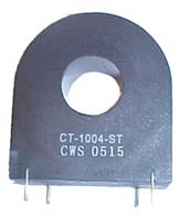
I just bought this today a CT up to 100AMPS it will be for a future PIC32
home energy usage monitor project for rainy days.
SCT 013 000 0 100A Non Invasive AC Current Sensor Split Core Current Transforme | eBay
I cannot confirm the circuit works if it does...
you need a fairly comfortable understanding of SMPS why dont you build something simple then move to bigger circuits you can still employee a CT and a TL 494 just not a HV mains version which may blow in your face with the slightest timing error.
- Status
- This old topic is closed. If you want to reopen this topic, contact a moderator using the "Report Post" button.
- Home
- Amplifiers
- Power Supplies
- Current Control Using TL494