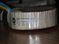
I have been given four 250VA toroidal transformers that came out of some active speakers, RCF Art 300A to be precise. I'd like to be able to reuse these but have one issue. The amplifiers in the RCFs were class G, quad rail (high/low +/-) and so the transformers in question are 60-30-0-30-60, dual 115V 50/60Hz primaries. Searching for the code# 81751094 gave me nothing. I have no use for the 60V windings, but the 30V are perfect for my needs.
My question, does anyone know if these are separate 30V windings configured under the insulating wrap in the above configuration? If so would it be reasonable to think I could reconfigure it to be a higher current 30-0-30 transformer by paralleling the appropriate windings?
Any insight appreciated, I'd like to avoid opening one up if there's no hope of getting what I need by doing so.
How many wires do you have on the secondary side?
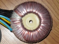
Just five externally, 60-30-0-30-60. Looking to find out if anyone knows a little about its specific construction. The secondaries appear to be all the same wire gauge, but there are two colours of lacquer visible that makes me think there may be two 30-0-30 windings that are in series. If possible I'd like to unwrap (NOT unwind) these to parallel them instead.
The different colours generally indicate that two spools of wire are being used while winding.
It can then be implied that the two colours are bi-fillar wound. This ensures that the number of Turns in the paralleled windings are identical.
You can check this by reversing one winding and get a zero volts readout. If there were a one Turn error, the readout would be the Volts/Turn value, usually between 100mVac and 1.5Vac.
Where the windings are tapped, it is usually possible to separate at the tapping point to end up with two separated windings.
You could end up with a 4 winding secondary, each at ~30Vac.
it's possible, why don't you post pictures so we can have a closer look?
Sure thing.
Attachments
This transformer look likes for "H" class amplifier.
Regards zeoN_Rider
You are correct, depending upon regional nomenclature regarding classes H and G. The amplifier module these used to power is what I would refer to as class G (dynamic rail boosting as opposed to hard rail switching). I'm not planning on creating one of the higher classes with these. I'd like to stick with class B/AB and thus the desire to see if I can set these up as 30-0-30 secondaries.
Sure thing.
you'll have to dig out that epoxy in the middle, i do it by cutting the mylar tapes on the outside and the thing will slide off...be very careful not to nick the magnet wires...
now you have to sever the connection point between the 60 and 30 volt taps and make them two separate windings so you can parallel them...
Here the PSU schematic.
Regards zeoN_Rider
Thanks for the effort zeoN_Rider, I had already sourced the schematics and am aware of what these were used for. Appreciated.
you'll have to dig out that epoxy in the middle, i do it by cutting the mylar tapes on the outside and the thing will slide off...be very careful not to nick the magnet wires...
now you have to sever the connection point between the 60 and 60 volt taps and make then two separate windings so you can parallel them...
I'll read from this that you think it is likely worth a shot. I'm out of time at the moment but will have a look at this later this evening to see. Thanks.

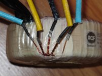
OK, It looks like I basically have either four 30V windings or two 30-0-30 in series, depending on how you look at it. Should be straight forward to modify the windings and tappings from series to parallel.
you are lucky indeed, no need to mess with the center filling...
you can feed the primary with 12 volts to get your secondary phasing right...
and if i were you, i'd just install individual pigtails no less than 6 inches long so that absolute flexibility is yours...
- Status
- This old topic is closed. If you want to reopen this topic, contact a moderator using the "Report Post" button.
- Home
- Amplifiers
- Power Supplies
- Possible to reconfigure Toroidal Transformer?