Hi. I have some distance between power-AMP and Torroid inside my enclosure. I need to use a longer cables between two blocks of PSU. Which one configuration will be the best concerning noise generated by cables:
1. AMP(local small cap) <-----------> BigCaps<-> rectifier<->Torroid
2. AMP(local small cap) <-> BigCaps <----------->rectifier<->Torroid
3. AMP(local small cap) <-> BigCaps <->rectifier<----------->Torroid
I need to note the PSU is inside a small enclosure with preamp and some LCD inside. I observed twice the trashy signs on the LCD. The LCD is mounted really close to the rectifier (and AC cables), and I am not sure now if this can be related to some high current spikes, or something different... Is it possible this PSU cables can impact TTL level on the LCD cables? This is like max 2-3 Ampers only...
I very much agree.1 will be best. 2 and 3 will be roughly equally bad, as both send charging pulses over a long cable.
The charging pulse circuit must be kept very compact and every effort taken to minimise effective loop area.
A figure of 8 loop as described by Dr Cherry is very effective in canceling the two loops that cannot be reduced to zero area alone.
Exactly what I though. The TTL couldn't not be so sensitive... I have exchanged the TTL cables to be sure this part not failed. But happened again yesterday. I observed once the LCD goes trashy. This happened most likely during some signal connection/disconnection. I get the hard 'knock' in the speakers is such moment (during power-on as well).
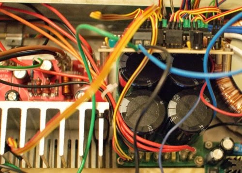
AndrewT, I don't know Dr Cherry description. Do you mean the loop between the traffo and rectifiers? It would fit to my example. For reference please look at the picture. As you can see my diodes block are not 'parallel' with the transformer. I mean the diodes and transformer cables do not make a symmetrical loops.

I see lots of pairs and quads.
All are close coupled.
If each pair is a flow and return then you have low loop area.
I see one 5wire. Are there separating grounds between signals?Again this could mean low loop area.
I see two red wires at the bottom separated. Where are the returns for these?
All are close coupled.
If each pair is a flow and return then you have low loop area.
I see one 5wire. Are there separating grounds between signals?Again this could mean low loop area.
I see two red wires at the bottom separated. Where are the returns for these?
The cables colors are definitely misleading. There is no ground between signals. Please have look on the 1'st photo. The thick arrow shows GND. The back arrows shows the signals current. Now I see there is not only a PSU cables optimal location, but signals may be a problem as well.... Two red cables are the +DC for power-amp. 2'nd photo shows more power-DC connections... Insane loops!
An externally hosted image should be here but it was not working when we last tested it.
Last edited:
Routing details are extremely important.
Always keep the power and ground pairs together, everywhere, as close as possible or twisted tightly together if possible. If you have space between them, they make better transmitting antennas. Similarly, any pairs that might pick up interference need to also be tightly twisted together, or else they will make better receiving antennas.
Always keep the power and ground pairs together, everywhere, as close as possible or twisted tightly together if possible. If you have space between them, they make better transmitting antennas. Similarly, any pairs that might pick up interference need to also be tightly twisted together, or else they will make better receiving antennas.
I just look at the commercial interfaces to have some reference. If we get e.g. the PATA cable for hardrive connection there is 7 grounds line in the 40-wire version. There are some decoupling between R/W signals like this:
Pin 22 Ground
Pin 23 I/O write
Pin 24 Ground
Pin 25 I/O read
Pin 26 Ground
In 80-wire version the GND is interleaved between every signal. I always though it is just to decrease impact of wires between each other, but this antennas is another reason I think. Anyway with PATA we have some huge transfers, comparing to my microcontroller.
BTW. I always see a problem with I2C transmissions is hearing in the speakers. Not really annoying and only when preamp parameters are changing. But I think it is probably different topic related to loops between digital and analogue GNDs.
- Status
- This old topic is closed. If you want to reopen this topic, contact a moderator using the "Report Post" button.
- Home
- Amplifiers
- Power Supplies
- PSU noise - distance between blocks - cables length