Good evening gentlemen,
I'm making calculations for the transformer of this amplifier (to aproximate the total costs of the wire) for the 28W at dual rail 23v at 3.7 amps bias.
I have allot of questions about these calculations so i'm asking help from all of the experimented coleagues of this forum with the calculations.
From the begining i'm telling you that i allready have a E+I (E20) sheets with the total thickness of the pack of 12cm.
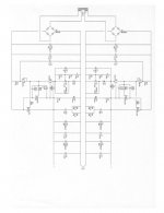
I want to use a capacitance multiplier like the one from the kaneda (image attached) so i have to make the Vrms of the transformer bigger. I was thinking that +-25V in the secondary of the transformer should be ok, and 11 amps, because i don't want the transformer to run hot, what do you think?
Please correct me in the below calculations because i dont want to fail.
Here i go:
1.
At this point i will calculate the total power that i need in the secondary:
Psec= 25V* 11A+25V* 11A => Psec=550W
2.
I need about 550W in the secondary (Psec=U*I <=> P=50*11<=>P=550W)
I have considered an efficiency of n=85%
Pp= Psec/n <=> Pp= 550/0.85=> Pp=650VA
Ip: I=P/U <=> I= 650VA/220V => Ip=2.96A
Note:
Pp : wattage absorbed by the primary;
Psec: secondary wattage;
Ip: current absorbed by the primary;
3.
Now, the total area (S) of the E+I that is needed to coope with such demands:
From what i read from books, i learned that we have a coeficient between 1.3 to 1.9 grades of usage for sqrt of Pp for the transformer:
- 1.3 coeficient ; 1.6 coeficient (medium usage); 1.9 coeficient (hight usage & stress of the transformer); I used the 1.9 coeficient because were talking here about class A amplification and i do not want to run the transformer hot;
S= 1.9*sqrt Pp <=> S=1.9*sqrt 650=>S=1.9*25.5=> S=48.5 square centimeters of E+I sheets.
4.
Now the thickness (h) needed for the transformer:
h= S/2*t (in cm) <=> h=48.5/2*2=> h= 12.1 cm
Note:
t: the type of E+I used (in my case i have the E20 wich means i have a width of 2cm);
5.
Turns per volt (n0):
E=4.44*f*N*O
O=Bm*S <=> O=0.9*48.5=>O=43.65 weber;
n0=N/E => n0= 1/4.44*f*O=> n0=(1/4.44*f*Bm) * 1/S <=>n0= (1/4.44*50*0.9)*1/S=> n0=0.0050/S (windings per volt);
If S mesures in square centimeters means that we have to transform n0= 50/S;
In my case, i have n0= 50/48.5 => n0= 1.03 turns per volt;
Note:
E: the effective value of the voltage in the winding that we choose;
f: frecvency of the input (in my case 50 Hz);
N: number of turns in the winding
Bm: the maximum value of the magnetic induction in the core (measured in T wich means tesla);
O: the maximum value of the magnetic flux in the core measured in Wb (weber);
6.
From point 5 i can calculate the total number of turns of the primary and secondary windings.
Np=n0*Up <=>Np=1.03*220=> Np= 227 turns for the primary;
Ns1 & Ns2= n0*Us=> Ns1 & Ns2= 26 turn per secondary winding (26 for Ns1 and 26 for Ns2); in total i have 52 turns for the secondary winding
7.
Now i want to calculate the diameters or the wire gauge:
From what i have read, we can choose a current density between 2A to 8A pe square mm; i have choosen 2A/square mm for all the windings (both secondary and primary). It it wisely to choose lower for the primary and higher for the secondary because the secondary windings are more ventilated than the primary.
We have the formula for the sectional area: Pi*square d
I/(Pi*square d/4) =2 (Amps/square mm);
From the above formulas results d=0.8*sqrt I;
From point 1 we have Ip=2.96 A and Isec=11A, wich means:
dp= 0.8*sqrt 2.96=> dp= 1.38 mm aprox 1.4 mm;
ds=0.8*sqrt 11=> ds=2.66 mm aprox 2.7 mm;
Note:
I: current density through the winding;
Pi=3.14;
d: wire gauge (dp & ds means primary and secondary gauge);
The other questions:
1. If i need 11 amps in the secondary means that i need 11A in +25 and 11A in the -25V winding or 5.5 amps in each of them?
2. The current in the secondaryes sum? If i wind with 2.66 gauge i will get 22 amps per total or 11A?
3. Are these calculations correct for the values of Ual listed at the begining? I'm interested in the results.. If they are unfamiliar to you all, could you calculate with your own formulas and then compare the results?
4. I want to couple this transformer with a capacitance multiplier (like in the Kaned amp PSU) so i want to make two separate windings, each wint 25 volts. The question here is: is there a problem if i wind bifilar (wind with two wires at the same time) the secondary windings?
5. Is there a problem if i use two turns of cooking papaer (rated at 250 degrees celsius) for the insulation between the layers (not between the primary and the secondary)?
6. Is it better to wind 1-5 turn in plus for the primary?
7. What kind of magnetic insulation wold be better for this transformer, a foil of copper above the secondary winding or two metal cases (one peace per side)?
8. Will the wire resulted from above fit in the transformer window (12 cm total thickness of the assembled sheets, E+I, E20)?---cand anyone help me with this?
I need your help so i beg of you to help me because i dont want to make a mistake in the calculations and spend money useless on wire.
Ps: please excuse my rough english.
I'm making calculations for the transformer of this amplifier (to aproximate the total costs of the wire) for the 28W at dual rail 23v at 3.7 amps bias.
I have allot of questions about these calculations so i'm asking help from all of the experimented coleagues of this forum with the calculations.
From the begining i'm telling you that i allready have a E+I (E20) sheets with the total thickness of the pack of 12cm.
I want to use a capacitance multiplier like the one from the kaneda (image attached) so i have to make the Vrms of the transformer bigger. I was thinking that +-25V in the secondary of the transformer should be ok, and 11 amps, because i don't want the transformer to run hot, what do you think?
Please correct me in the below calculations because i dont want to fail.
Here i go:
1.
At this point i will calculate the total power that i need in the secondary:
Psec= 25V* 11A+25V* 11A => Psec=550W
2.
I need about 550W in the secondary (Psec=U*I <=> P=50*11<=>P=550W)
I have considered an efficiency of n=85%
Pp= Psec/n <=> Pp= 550/0.85=> Pp=650VA
Ip: I=P/U <=> I= 650VA/220V => Ip=2.96A
Note:
Pp : wattage absorbed by the primary;
Psec: secondary wattage;
Ip: current absorbed by the primary;
3.
Now, the total area (S) of the E+I that is needed to coope with such demands:
From what i read from books, i learned that we have a coeficient between 1.3 to 1.9 grades of usage for sqrt of Pp for the transformer:
- 1.3 coeficient ; 1.6 coeficient (medium usage); 1.9 coeficient (hight usage & stress of the transformer); I used the 1.9 coeficient because were talking here about class A amplification and i do not want to run the transformer hot;
S= 1.9*sqrt Pp <=> S=1.9*sqrt 650=>S=1.9*25.5=> S=48.5 square centimeters of E+I sheets.
4.
Now the thickness (h) needed for the transformer:
h= S/2*t (in cm) <=> h=48.5/2*2=> h= 12.1 cm
Note:
t: the type of E+I used (in my case i have the E20 wich means i have a width of 2cm);
5.
Turns per volt (n0):
E=4.44*f*N*O
O=Bm*S <=> O=0.9*48.5=>O=43.65 weber;
n0=N/E => n0= 1/4.44*f*O=> n0=(1/4.44*f*Bm) * 1/S <=>n0= (1/4.44*50*0.9)*1/S=> n0=0.0050/S (windings per volt);
If S mesures in square centimeters means that we have to transform n0= 50/S;
In my case, i have n0= 50/48.5 => n0= 1.03 turns per volt;
Note:
E: the effective value of the voltage in the winding that we choose;
f: frecvency of the input (in my case 50 Hz);
N: number of turns in the winding
Bm: the maximum value of the magnetic induction in the core (measured in T wich means tesla);
O: the maximum value of the magnetic flux in the core measured in Wb (weber);
6.
From point 5 i can calculate the total number of turns of the primary and secondary windings.
Np=n0*Up <=>Np=1.03*220=> Np= 227 turns for the primary;
Ns1 & Ns2= n0*Us=> Ns1 & Ns2= 26 turn per secondary winding (26 for Ns1 and 26 for Ns2); in total i have 52 turns for the secondary winding
7.
Now i want to calculate the diameters or the wire gauge:
From what i have read, we can choose a current density between 2A to 8A pe square mm; i have choosen 2A/square mm for all the windings (both secondary and primary). It it wisely to choose lower for the primary and higher for the secondary because the secondary windings are more ventilated than the primary.
We have the formula for the sectional area: Pi*square d
I/(Pi*square d/4) =2 (Amps/square mm);
From the above formulas results d=0.8*sqrt I;
From point 1 we have Ip=2.96 A and Isec=11A, wich means:
dp= 0.8*sqrt 2.96=> dp= 1.38 mm aprox 1.4 mm;
ds=0.8*sqrt 11=> ds=2.66 mm aprox 2.7 mm;
Note:
I: current density through the winding;
Pi=3.14;
d: wire gauge (dp & ds means primary and secondary gauge);
The other questions:
1. If i need 11 amps in the secondary means that i need 11A in +25 and 11A in the -25V winding or 5.5 amps in each of them?
2. The current in the secondaryes sum? If i wind with 2.66 gauge i will get 22 amps per total or 11A?
3. Are these calculations correct for the values of Ual listed at the begining? I'm interested in the results.. If they are unfamiliar to you all, could you calculate with your own formulas and then compare the results?
4. I want to couple this transformer with a capacitance multiplier (like in the Kaned amp PSU) so i want to make two separate windings, each wint 25 volts. The question here is: is there a problem if i wind bifilar (wind with two wires at the same time) the secondary windings?
5. Is there a problem if i use two turns of cooking papaer (rated at 250 degrees celsius) for the insulation between the layers (not between the primary and the secondary)?
6. Is it better to wind 1-5 turn in plus for the primary?
7. What kind of magnetic insulation wold be better for this transformer, a foil of copper above the secondary winding or two metal cases (one peace per side)?
8. Will the wire resulted from above fit in the transformer window (12 cm total thickness of the assembled sheets, E+I, E20)?---cand anyone help me with this?
I need your help so i beg of you to help me because i dont want to make a mistake in the calculations and spend money useless on wire.
Ps: please excuse my rough english.
Attachments
- Status
- This old topic is closed. If you want to reopen this topic, contact a moderator using the "Report Post" button.