<snipped>
Regarding capacitance. After some more reading about GC I see there ware a versions with only 1000uF per rail (with 200VA transformer), so this is all subjective thing ...
<snipped>
Not quite. The capacitance determines what you can say the rated max output power is. For a given rated max power, there is a minimum capacitance, below which the amplifier will clip for a sine signal at or above the rated max power.
Remember that the load, for each rail of the power supply (with a class AB amplifier), is the amplifier in series with the speaker, not just the speaker. The dropout voltage is the minimum voltage between the amplifier power pin and the amplifier output pin.
The rail voltage minus the ripple voltage minus the amplifier clipping (i.e. dropout) voltage must be greater than the peak output signal voltage. Otherwise, the ripple voltage will intrude down into the voltage space that is normally occupied by the amplifier, and will gouge ripple-shaped chunks out of the signal voltage waveform.
Attached is a spreadsheet that calculates the minimum required capacitance in two ways. One way assumes the absolute-worst-case signal, i.e. DC at the peak level of a sine output, for a given rated maximum output power. That way gives a "bulletproof" minimum capacitance that will never allow clipping, even for every non-sine signal. The second way uses the maximum RMS sine voltage, instead of the peak. If you need to minimize the capacitance needed, the second way should usually be "good-enough".
Also remember that the system will probably be somewhat more than 50% efficient, i.e. somewhat less than HALF of the power will be wasted, as heat. So I do not believe that 1X the rated maximum output power would be suitable, for a transformer VA rating. I would always want to use AT LEAST 2X the rated max amplifier output power, for the transformer VA rating.
Attachments
Last edited:
150VA on 220Vac needs T625mA or T800mA fuse.for a 150va traffo a soft start circuit is not really needed....if you have a power switch rated for at least 10amps.
Why use a bigger fuse and a bigger switch to save the cost of the soft start?
150VA on 220Vac needs T625mA or T800mA fuse.
Why use a bigger fuse and a bigger switch to save the cost of the soft start?
because switches are much simpler and cheaper for a newbie.....and fuses are likewise dirt cheap...
a DPST switch similar to the one shown below is rated for 8amps...
besides, the dc resistance of this size of traffos are high enough to allow switches only imho...
An externally hosted image should be here but it was not working when we last tested it.
First of all I totally forgot about the fuses, and rated power on for eventual switch. I would like to control the power-amp stage PSU with relays, to have a stand-by mode. This GC will be extension for pre-amp built many years ago. I see I need consider some high current topics yet .. So Tony you say there will be some about 10Amp kick at the start...
I faced another design problem.. pre-amp is powered from a low voltage transformer (will be replaced with 150VA), and there is lm7805 an lm7812 voltage regulators. I made a test with my new transformer which gives about 35V DC (this is maximum input voltage for this chips) and they go really hot! I need to consider a separate mini -PSU for that..
I faced another design problem.. pre-amp is powered from a low voltage transformer (will be replaced with 150VA), and there is lm7805 an lm7812 voltage regulators. I made a test with my new transformer which gives about 35V DC (this is maximum input voltage for this chips) and they go really hot! I need to consider a separate mini -PSU for that..
I would like to have such ratio, but I have a limited space for transformer in my case. The space for capacitors are limited as well... I fight with the space, and will see If I can get about 2x40W continuous power output...AT LEAST 2X the rated max amplifier output power, for the transformer VA rating.
.. So Tony you say there will be some about 10Amp kick at the start...
it will be only a few cycles, energy content is low and nothing to worry about...
I faced another design problem.. pre-amp is powered from a low voltage transformer (will be replaced with 150VA), and there is lm7805 an lm7812 voltage regulators. I made a test with my new transformer which gives about 35V DC (this is maximum input voltage for this chips) and they go really hot! I need to consider a separate mini -PSU for that..
you do, you were trying to lose about 23volts on the regulator so you are wasting power that way....what is wrong with the old setup? if you have space i would leave it alone...
I would like to have such ratio, but I have a limited space for transformer in my case. The space for capacitors are limited as well... I fight with the space, and will see If I can get about 2x40W continuous power output...
i have no doubt that you can get that power with a 150va traffo..
The old one PSU was a transformer (50VA) with some kind of stand-by module. This transformer is too big to put together with the new one. The stand-by module is something which maybe will be redesigned. Of course if I go in that direction to enable/disable power-amp, but your suggestion with the ON/OFF switch is really attractive too (less work to do).
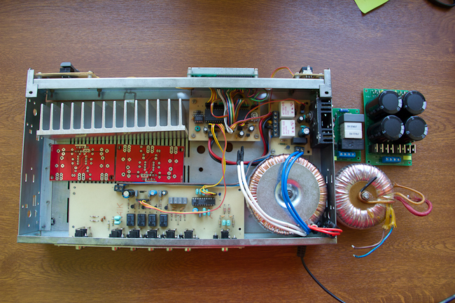
Please look at the picture. Now when I know the PSU condensers are required to provide 'solid' voltage for power-amp, this makes even less space for everything. (on the right area the old trasformer, the soft-start module and capactitors module). I am thinking to maybe put some modules vertically. No doubts I can't do anything with connectors (module on the backplane). It is too much adjustments at this moment (even if this upgrade with GC is a great fun I have somehow limited time for that).
If you can see, there is no any fuses and power-cord is without 'grounding' (and would be nice to have some space the socket). Even if the safety is first, I will think about the cord later.
I need to change the approach to heat sink as well, and probably cut this on two parts, to have more compact area. The GC will be put on the left because there is better ventilated area. But this is another story ...
Thanks for any suggestions. This PSU is still some kind of challenge!
Last edited:
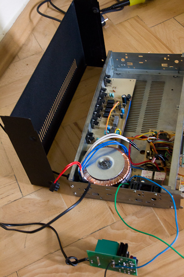
This is more classical case. There is a black cover. The photo 'describes' this better. I will stick with heat sink inside.
I started test with the small transformer for pre-amp with nominal 12V 4VA. It is funny how voltage drops when I take current. Normally with stand-by off (takes about 30mA) the AV voltage is 15V, and when I enable pre and display which takes about 370mA the AC on the transformer drops to 12V.
One more notice. I needed to drop down a back-light current for LCD from 100mA to about 60mA with serial resistor, because the situation with voltage drops was even worse and I couldn't really get 12V after regulator. Anyway this is not a super stable solid PSU. Maybe I should think about bigger condensers like in case of power-amp toroid. Now I have 2x 470uF, and could exchange this to 2x1000uF. I feel every voltage counts..
AndrewT I measured the 370mA on the AC line.
The transformer model: 'tez 4.0/d 12v 4va' 0,33A (fuse symbol) 0,4A . It is overloaded comparing to nominal 0,33A but not so much (about 10%).
How this is possible your current value is so small on the DC? Is not that just P=UI?
The transformer model: 'tez 4.0/d 12v 4va' 0,33A (fuse symbol) 0,4A . It is overloaded comparing to nominal 0,33A but not so much (about 10%).
How this is possible your current value is so small on the DC? Is not that just P=UI?
There are dozens and maybe hundreds of posts, telling you how to work out the maximum continuous AC current into a resistor load.
There will also be dozens of posts telling you that loading a transformer with a capacitor input filter is VERY DIFFERENT.
P=Vac*Iac does NOT apply to a capacitor input filter.
There will also be dozens of posts telling you that loading a transformer with a capacitor input filter is VERY DIFFERENT.
P=Vac*Iac does NOT apply to a capacitor input filter.
should be written as 0.33Aac. it is the AC rating when loaded with a resistor.0,33A
Yes of course. I should now that.
Can I assume the phase of impedance is something like 45 degrees ? From calculation it will give 0.33Aac/rt(2) ~= 0.23Aac for resistive part. Is that what I can get to keep the transformer in good condition?
Oh I just realized if I go for more condensers I increase a reactance, and this phase may be even bigger...
Last edited:
AndrewT I measured the 370mA on the AC line.
The transformer model: 'tez 4.0/d 12v 4va' 0,33A (fuse symbol) 0,4A . It is overloaded comparing to nominal 0,33A but not so much (about 10%).
How this is possible your current value is so small on the DC? Is not that just P=UI?
strange that you want to measure that, is your traffo overheating? if not then it is not an issue...
resistors as an ac load has unity power factor...the 370mA you measured will have several components, part goes to heating up your traffo and part just energy storing components...
temperature is OK. It is worm and I can attached hand to it.
Somehow we skipped from big power traffos to small powers. The rules should be the same I think. Nevertheless forget about the ampers for the moment. With this trafo I have:
stby off: 15,8vac -> 19,3vdc (after diode bridge + 1x470uF filter)
stby on: 12,1vac -> 12,5vdc (after diode bridge + 2x470uF filter)
I realized now that this 12,5vdc is not enough for my 12V voltage regulator (because of voltage drop) and I get 11V at the end. I have relays for input switching on 12V coils (works fine with 11V), and TDA8425 which has a minimal supply voltage 10.8V, but typical 12V... I consider this transformer as too small and use as temporary solution. Maybe I will go for 10va to have some reserve.
This all tests are without any audio signal attached, just a PSU observation.
I have another doubt. Is it OK to skip the capacitors near the chip on the power lines, if I have such huge capacitance in the PSU? I am asking, because maybe I will change the heat-sink to something like this on the photo.
I see difficulties to dissipate the heat in my small enclosure. It is probably like 25W-30W heat to dissipate. From my general calculation I need about 2C/W (or even smaller) for the heat-sink per channel (assuming 1C/W for chip case, 0.5C/W between case and heat-sink, and 40C ambient temp). This one on the photo is still small, but gives me more compact area if I put the GC PCBs back-to-back (with two such heat-sinks vertically).

I see difficulties to dissipate the heat in my small enclosure. It is probably like 25W-30W heat to dissipate. From my general calculation I need about 2C/W (or even smaller) for the heat-sink per channel (assuming 1C/W for chip case, 0.5C/W between case and heat-sink, and 40C ambient temp). This one on the photo is still small, but gives me more compact area if I put the GC PCBs back-to-back (with two such heat-sinks vertically).
The 0.1uF decoupling will be in place near the chip. I remember from digital electronic circuits it is good practice to use such decoupling on power lines.
I connected the amp to PSU with serial 60w bulb on 230vac line and soft-start. I am using a second version of PSU here which has a fuses on the PCB (is bigger in size, not sure if final, but I am addicted from Farads now it have 2x15F per rail). No explosion, no strange smell. Little heat on heat sink (still clean-aluminium). No DC offset on the amp outputs. So far so good.
The datasheet shows some low value capacitors which blocks eventual high-freq osculations. I didn't implemented this due to missing parts. There is option on the PCB to add them and not sure if required in my case but maybe better to be on the safe side.
The small cap is necessary (i.e. not optional) for high-frequency bypassing, for stability. It should be connected _extremely_ close to the chip's power pin and load gnd, e.g. within a mm or two. The capacitance value is not as important as having the shortest-possible connections. It's usually best to find a cap that will fit directly across the pins and then use the largest value available in that case size. An X7R ceramic is usually the safest, there, in terms of not accidentally causing HF resonances. But a film cap could perform better. You could try both and see if there is any difference in the chip's temperature. A higher chipamp temperature under similar conditions would probably mean that there was high-frequency oscillation, or even just excessive HF ringing, in which case you would probably want to switch back to the X7R ceramic.
You will definitely also want a few hundred uF (probably at least 470 uF) in parallel with that small cap, so that fast-rising transient currents do not have to try to come through the inductance of the power and ground rails. Try to get the electrolytic cap within a cm or so of the pins.
We could calculate the minimum decoupling capacitance needed, and the maximum inductance that could be tolerated in the decoupling network (calculating either in the time domain with differential equations and transient current specs etc, or, in the frequency domain for the maximum tolerable impedance seen by the power pins in order to have some max delta V due to the worst-case delta I, giving Z = dV/dI, which usually needs to be good out to a few hundred kHz, for a chipamp), which (the max inductance) basically equates to maximum allowable connection lengths plus cap lead spacing. But 470 uF within a cm or so should usually be OK, for a chipamp. But, if you can fit more of those in parallel, even a little farther away, then do it.
I mean 15mF, not 15F in the previous post (this would be huge!)
The 470uF somehow kills my idea with heat-sink on the PCB side (please see a picture). I see I purchased too much universal PCBs for GC where area for decoupling is too big for my case (C10 has 25mm). I will waste some space here. The C8 and C9 is in place. Not so close as you described.
Electronic correctness is more important here. I will follow an advice with 470uF. The impedance will be noticeable between PSU and GC PCBs. The precise calculation will not be necessary this approximated values looks OK.
Thanks.
Last edited:
Finally I made some measurements with connected load (3 x parallel 18R / 20W). I was able to use oscilloscope and in deed the small capacitors was necessary to cancel same oscillations. Between + and - input (220p) cancels some hi-freq oscillations with same amplitude as signal. Second one (10pF connected parallel with resistor in the amp loopback) cancels small 400mV 750khz oscillations on the output.
I disconnected the safety-bulb. The amp sometimes loose the signal if I make an output voltage bigger than 17V p-p. This is like switching 3 seconds output wave, and 3 secs 0V. This is probably chip overheating (?). Later I lost my fuse on -35V rail which was rated 1.5A (delayed one) so I need to get a new one.
I disconnected the safety-bulb. The amp sometimes loose the signal if I make an output voltage bigger than 17V p-p. This is like switching 3 seconds output wave, and 3 secs 0V. This is probably chip overheating (?). Later I lost my fuse on -35V rail which was rated 1.5A (delayed one) so I need to get a new one.
- Status
- This old topic is closed. If you want to reopen this topic, contact a moderator using the "Report Post" button.
- Home
- Amplifiers
- Power Supplies
- transformer power for gainclone amp