Given what digitaljunkie says and which is plausible, I would add some suitable good old RC filtering at each output.The outputs appear to have LC filtering,the voltage before them will be more-or-less the same as the output. (The DC Resistance of the coils is low,so there's not a large voltage drop across them.)
Also, this appears to be 'positive ground' or a -9V supply. (The inside 'tip' of the jacks is negative,and the outer barrel,or 'ring', is positive. Thus,the LC filters are in the negative side of the circuit -this may be a cause of ground loops.)
Something like soldering 470 to 2200 uF across *each* ouput jack, and adding , say, 1 ohm in series wiyh each positive wire, straight at the jack.
Or , "Plan B": junk that PSU and buy/build a classic one.
One of the few cases where Plan B is much better than the original one.
Given what digitaljunkie says and which is plausible, I would add some suitable good old RC filtering at each output.
Something like soldering 470 to 2200 uF across *each* ouput jack, and adding , say, 1 ohm in series wiyh each positive wire, straight at the jack.
Or , "Plan B": junk that PSU and buy/build a classic one.
One of the few cases where Plan B is much better than the original one.
Could I just up the 10uf to 1000uf leave the 0.1uf in and leave that 160ohm in on each output. I'm told that should get the corner frequency down. I just put it through an rc calculator makes sense.
Attachments
Couldn't I put and in7816 diod in parallel before the output to protects against reverse-polarity.
Could I up the main filter after tranny if it's called that? the 470uf to 1000uf. I just noticed a mistake in my values as well thats a .1uF across the 470uf not a 10uf (C1).
Could I up the main filter after tranny if it's called that? the 470uf to 1000uf. I just noticed a mistake in my values as well thats a .1uF across the 470uf not a 10uf (C1).
and leave that 160ohm in on each output.
What 160ohm resistors are you talking about? If you mean those greenish looking things, I don't think those are resistors - they look like inductors to me.
Yeah, if they're 160 uH, then try a large-ish capacitor connected just downsteam, and also connected to the other side of the output. 1000 uF to 2200 uF should be VERY effective, with 160 uH. But the more capacitance the better. A 16V 2200 uF cap should measure about 12.5 mm diameter x 25 mm tall (so 1/2-inch wide and 1 inch tall), with 5 mm lead spacing (just under 1/4-inch), and will probably cost around a dollar each. A 1000uF 16V cap would be about 10 mm diameter x 20 mm tall, with 5 mm lead spacing.
It looks like they already have caps there, to do the LC filtering, and we're assuming their caps are not large-enough in value. What value did they use there? And what is the lead spacing in mm? You should be able to either replace their caps with larger ones, or just solder the larger ones in parallel with theirs.
It looks like they already have caps there, to do the LC filtering, and we're assuming their caps are not large-enough in value. What value did they use there? And what is the lead spacing in mm? You should be able to either replace their caps with larger ones, or just solder the larger ones in parallel with theirs.
Last edited:
Theres a 10uF and a 0.1uF I don't why they did that maybe it kept cost down.
I haven't really explained how bad the hum is on this power supply it is pretty much unusable. It has a hum but also has crackle higher up the spectrum. And I know its not a fault as I've known for other people with the same problem only with this power supply. But it's so loud is ridiculous.
I've ordered some 2200uf 16v low esr caps. Hopefully it'll sort this power supply out.
Theres a 10uF and a 0.1uF I don't why they did that maybe it kept cost down.
Paralleling larger electrolytic caps with smaller caps like so is a common practice.
Hey, be really careful when checking this supply - it sounds as though you don't have much experience and I just wanted to pass along to you that switching supplies are much more DANGEROUS to work on than linear supplies when they are plugged in and running.
The mains voltage is not transformer isolated on this supply as it would be with a linear supply. So - you have to be extremely careful where you place your multimeter probes, let alone your fingers.
Honestly, I would say scrap this project, live and learn - use the box to house a better, quieter and safer linear supply.
Agree on scrapping it.
The basic idea is not bad, of course, but was very poorly implemented.
Meaning a **pedal** PSU , meaning audio processors which later are plugged into a high gain amp (typical guitar amp) is a mess.
I suspect some obscure Chinese factory is making some $$$ churning out cheap smps cellphone chargers and such, where ripple/hum/buzz don't matter and all, and said "let's make yet another application of this cheap technology"
it's actually made by this company even though it says soundlabs on it.DJ and Disco Equipment by NJD Electronics, Manufacture and Sale of Professional DMX DJ lighting, DJ Speakers, Professional DJ Lighting, LED Starcloth, Mirage LED lighting and Professional Speakers.
I don't plan on taking any measurements went its powered up again. I've ordered the new caps now so we'll see how it goes. Need it ready for a gig on monday.
I don't plan on taking any measurements went its powered up again. I've ordered the new caps now so we'll see how it goes. Need it ready for a gig on monday.
Paralleling larger electrolytic caps with smaller caps like so is a common practice.
I actually meant that the 10 uF is a very small value for the filter. If this makes this supply usable then it's stupid the manufacturer didn't make it like this in the first place.
Put in 2200uF caps today, all noise has gone almost completely, it's actually very quiet now even with 3 distortion pedals on. There's plenty of room in the chassis for the caps so it was an easy change.
Thanks for everyones help and knowledge. I've read up on linear and smps supply's as well as rc filtering and hi/low pass filtering for audio.
Thanks for everyones help and knowledge. I've read up on linear and smps supply's as well as rc filtering and hi/low pass filtering for audio.
Congratulations!
Yes, 10 uF was a stupid, stupid value. Probably another case of the bean counters "ruling the roost", because the engineers never became masters of interpersonal communication (long story; see Jan Didden's blog, "Don't be such a scientist". Excellent reading.)
Yes, 10 uF was a stupid, stupid value. Probably another case of the bean counters "ruling the roost", because the engineers never became masters of interpersonal communication (long story; see Jan Didden's blog, "Don't be such a scientist". Excellent reading.)
Ok now I have another problem. I'm getting what I can only describe as intermittent or pulsating current or voltage. I'm yet to measure what's happening at the socket. If I have all the pedals plugged in and power up it happens but if I power up without the pedals in then plug in one by one its fine?
If I use my delay which draws more amps the supply is rated for it introduces noise so I'll run that off a separate supply.
Would it be a good idea to run through my power condition when using it.
If I use my delay which draws more amps the supply is rated for it introduces noise so I'll run that off a separate supply.
Would it be a good idea to run through my power condition when using it.
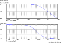
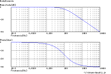
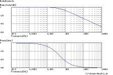
Well, there is a resonant peak in the LC response (at 200-300 Hz, probably). You could put a resistor in series with each of the 2200 uF caps (might be a pain). 1K would actually work. Almost any value would work but 1K would ensure not much dissipation, so you could be safe using a 1/4-Watt size.
- Status
- This old topic is closed. If you want to reopen this topic, contact a moderator using the "Report Post" button.
- Home
- Amplifiers
- Power Supplies
- Help cleaning up ripple on 9v 6 chnl guitar pedal power supply