Hello all,
I am currently building (cobbling together) a hybrid integrated amp.
The tube pre-amp board requires ~12v AC
The amp board (Tripath 2020) requires ~12v DC
I currently have:
- 110/120vac-to-12vac transformer rated at 3.33 amps
- 110/120vac-to-12vdc transformer rated at 2 amps
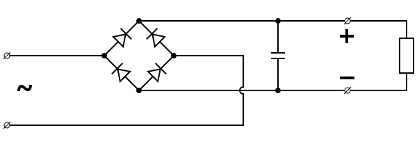
It all works quite well during testing (see photo), however I would like remove the DC supply and implement a simple rectifier between the 12vac supply and the amp board.
I have read and understand the theory of a diode bridge and output smoothing. Diode bridge - Wikipedia, the free encyclopedia
I have a box full of spare parts with all kinds of the square metal bridge rectifiers and capacitors.
Is it as simple as hooking the 12vac leads to the AC terminals of the bridge rectifier and then connect the load to the DC terminals, with a large capacitor in parallel?
I am currently building (cobbling together) a hybrid integrated amp.
The tube pre-amp board requires ~12v AC
The amp board (Tripath 2020) requires ~12v DC
I currently have:
- 110/120vac-to-12vac transformer rated at 3.33 amps
- 110/120vac-to-12vdc transformer rated at 2 amps
It all works quite well during testing (see photo), however I would like remove the DC supply and implement a simple rectifier between the 12vac supply and the amp board.
An externally hosted image should be here but it was not working when we last tested it.
I have read and understand the theory of a diode bridge and output smoothing. Diode bridge - Wikipedia, the free encyclopedia
I have a box full of spare parts with all kinds of the square metal bridge rectifiers and capacitors.
Is it as simple as hooking the 12vac leads to the AC terminals of the bridge rectifier and then connect the load to the DC terminals, with a large capacitor in parallel?
Last edited:
By the way, the pre-amp board only draws a max of .833 amps from the 12vac supply, which would leave 2.5 amps for the amp board, which is still more current than the dedicated 12vdc supply.
Another question; with that huge Mallory in the picture, is a paralelled "output smoothing" cap still necessary?
Another question; with that huge Mallory in the picture, is a paralelled "output smoothing" cap still necessary?
Last edited:
If you rectify 12V AC RMS you get about 16V DC, not 12V DC.
Interesting. This seems important!
So the next question is, how to I bring that back down to 12v? Resistance?
Looks like I found my answer... http://www.raltron.com/cust/tools/voltage_divider.asp
But if you have any other pointers, I'd be happy to hear them.
")
Last edited:
No. More like a 10,000 uF cap in series with a small amount of inductance and resistance. If there's decoupling on the PCB, those wires aren't that big of a deal. It's not pretty, it's not good engineering practice, but it will work perfectly fine. In no case does the capacitance change!That longass wires to the cap is like 1000uf cap on pcb.
+1If you rectify 12V AC RMS you get about 16V DC, not 12V DC.
Since the OP doesn't seem to understand this, the formula would be 1.414 x 12, minus two diode drops.
Voltage regulator. But, most cheap and dirty three terminal regulators won't do the job because of the 4 volt drop.So the next question is, how to I bring that back down to 12v? Resistance?
Not hardly. This isn't viable for more than milli-amps.Looks like I found my answer... Voltage Divider Calculator
Last edited:
No. More like a 10,000 uF cap in series with a small amount of inductance and resistance. If there's decoupling on the PCB, those wires aren't that big of a deal. It's not pretty, it's not good engineering practice, but it will work perfectly fine. In no case does the capacitance change!
This is what my gut was telling me, but I don't know much about electronics so I decided to keep my mouth shut.
Voltage regulator. But, most cheap and dirty three terminal regulators won't do the job because of the 4 volt drop.
Not hardly. This isn't viable for more than milli-amps.
Hmmm. OK. Well, I really only need to drop down to 14 volts. Not sure how much that changes things.
Why don't you use a voltage regulator?
Because I have no idea what I am doing, basically, and I am frugal.
If I can cobble something together from my box of components, then I'd rather do it that way.Edit: I just looked on ebay and it appears as though a voltage regulator is as big or bigger than the existing DC supply I already have in there.
The point is to get rid of the DC supply and get ~13.5v DC from the 12v AC supply with the fewest, cheapest components, many of which I probably have in my box o' goodies.
Last edited:
Cheap and dirty solution: A few diodes in series. They drop about .65V a piece for plain old silicon. I'd use 6 in case of high line. The voltage rating (PIV) doesn't matter. Switching performance doesn't matter. Standard cheap silicon diodes are fine. Current rating does matter. I'd use a 6 amp diode. (Anywhere from 5 to 10 should be okay.)Hmmm. OK. Well, I really only need to drop down to 14 volts. Not sure how much that changes things.
Cheap and dirty solution: A few diodes in series. They drop about .65V a piece for plain old silicon. I'd use 6 in case of high line. The voltage rating (PIV) doesn't matter. Switching performance doesn't matter. Standard cheap silicon diodes are fine. Current rating does matter. I'd use a 6 amp diode. (Anywhere from 5 to 10 should be okay.)
Nice! I have some diodes laying around. Not sure on the current ratings, but I'll see what I have and do some tinkering.
Thanks!
On second thought... Your preamp may require an isolated supply. Without seeing the schematic, I can't be sure. You may wish to just leave things as it is.
Will I damage it by trying, or will it simply not work? It's a $22 board, so I'm not super paranoid about it. I can always revert back to dual supplies...
A part of me just wants to see if I can do it.
Know the feeling?
Why do you want to get rid of the second supply? If I may ask
I dunno. It just seems so... superfluous.
Also, the larger supply has more reserve juice available for the amp, which is never a bad thing for these TA2020 chips (AFAIK).
But mostly... because I want to see if I can build a rectifier and make it work.
I'm one of those dangerous people with no formal electronics training and way too much enthusiasm and spare parts.

Without seeing the schematic, I can't say. I'd assume that it'll trash both the amp and the pre-amp to be safe.Will I damage it by trying, or will it simply not work? It's a $22 board, so I'm not super paranoid about it. I can always revert back to dual supplies...
- Status
- This old topic is closed. If you want to reopen this topic, contact a moderator using the "Report Post" button.
- Home
- Amplifiers
- Power Supplies
- Simple DIY Rectifier?