Hi folks. I am new to the forum, and my question is not strictly audio but close. I have a power supply I built 30 years ago to power an electromagnet on a home built magnetic drill press. Consisted of a rectifier bridge from a GM car alternator, a 200 mfd motor start capacitor and a 3/8" diameter 9" long steel rod with about a couple hundred turns of 18 ga magnet wire around it as an inductor to help smooth the voltage. The input was direct (fused) from the 120 VAC. It worked fine for years. Then my magnet burned out and I put it aside for a few decades.
I recently found a few spare moments and made a new bigger magnet using a full 10 pound spool of 22ga magnet wire stuffed into a welded cylindrical magnet housing. Has 80 ohms resistance and draws about 2 amps at the 160 v or so DC output from my power supply. Works great generates huge amount of pull.
My problem is the inductor in the power supply is getting quite warm (hot actually) which I do not recall being a problem when used with the old magnet. I don't remember what the old magnet drew, but I know it was a lot less as it was 1/5 the physical size of the current one. The inductor rod buzzes a fair amount, which I don't remember it doing in the former incarnation of my device .
What are the easy solutions - make a bigger inductor - longer? - more turns? - heavier wire? I think the heat is coming from the "induction" action in the core, not resistance in the wire as it is much larger gauge wire than used in the magnet the power supply is driving. One other possible factor is the power supply is now mounted on the drill press itself within a few inches of the magnet so maybe being in the magnetic field of the magnet is having some effect?
Any suggestions would be appreciated. I am not an engineer - I'm a beanie by training and worked as a marketing guy for years, but am moderately handy with simple electronics.
My problem is the inductor in the power supply is getting quite warm (hot actually) which I do not recall being a problem when used with the old magnet. I don't remember what the old magnet drew, but I know it was a lot less as it was 1/5 the physical size of the current one. The inductor rod buzzes a fair amount, which I don't remember it doing in the former incarnation of my device . What are the easy solutions - make a bigger inductor - longer? - more turns? - heavier wire? I think the heat is coming from the "induction" action in the core, not resistance in the wire as it is much larger gauge wire than used in the magnet the power supply is driving. One other possible factor is the power supply is now mounted on the drill press itself within a few inches of the magnet so maybe being in the magnetic field of the magnet is having some effect?
Any suggestions would be appreciated. I am not an engineer - I'm a beanie by training and worked as a marketing guy for years, but am moderately handy with simple electronics.
Hilited is the probable reasoning. It sounds like the solid steel rod is dissipating at 120 hz. I would recommend re-doing the inductor using lots of individual smaller steel insulated rods. It is probably eddy current dissipation in the inductor, and using lots of smaller insulated rods will break that up.
jn
Thanks, I'll try that. Would 1/32 inch or so wires in a. 1/2" bundle be "many" enough to be effective?. I would cut some pieces out of tig welding filler and spray them with insulating enamel.
I don't know if tig filler is magnetic. But yes, I'd spray. Oxidized as OdB said may be good enough, but I wouldn't trust it.
I'd try to duplicate the total cross sectional area so the inductance is similar. But since you're winging it for no exact inductance value, give it a try. Remember, the inductance goes up as the square of the number of turns, so if you're too low in inductance, just add more turns.
jn
This would be true if there exists AC voltage and current though the col, but if there is only DC, the current is dominated by wiring resistance. IN DC inductance if of no means excepting in transients of switching on or off. Be sure what are you apliying to this electro-magnet.Remember, the inductance goes up as the square of the number of turns, so if you're too low in inductance, just add more turns.
jn
Why do you use in inductor is series with what is essentially a very large inductor the magnet? The magnet itself is a very effective filter many electromagnet power supplies are unfiltered, for a full wave single phase bridge rectifier with no capacitor input filter the average DC voltage across the magnet will be 0.9 x the supply voltage. With 80 ohms just over an amp will flow. That would reduce the magnet heating from around 300W to 145W. The important thing is how hot the magnet gets for me I would get rid of the capacitor input filter and the inductor and see how that works, there is many a shunt wound DC motor or magnetic chuck using no filtering.
This would be true if there exists AC voltage and current though the col, but if there is only DC, the current is dominated by wiring resistance. IN DC inductance if of no means excepting in transients of switching on or off. Be sure what are you apliying to this electro-magnet.
A few points:
First, he used an automotive alternator bridge to rectify the line. I do not recommend such for a very good reason..Automotive bridges are typically designed to be capable of what is referred to in the industry as "load dump". This occurs if for example, when a low battery is disconnected while it is heavily charging. The voltage regulator controls the rotor current in order to modulate the outut voltage of the field coils. Because the rotor is inductive, it cannot be instantly turned off in the event all load is disconnected. As a result, the 12 volt DC distribution system in the car can climb to 80 volts as a transient. The testing/screening requirements at the alternator "button" rectifier manufacturer (previous employ) was 80 volts at 125 degrees C, typical automotive environment under the hood. Under no circumstances are alternator rectifiers tested nor designed to be used off-line at 120 vrms. Off line silicon is typically designed for bvr's of 600 (old school) to 800 volts (current thinking).
Second, he has a 200 uf capacitor. If the bridge feeds the capacitor directly, then what you state is closer, the series connection will dominate. If the inductor is between the bridge and the cap, the charging pulses will be going through the hand would inductor. That is why I mentioned 120 hz, as that would be the primary dissipative component. edit: Also of consideration is the cross sectional area of the load magnet. If it is solid iron, it will eddy to beat the band and as such, will result in lower inductance at frequency, forcing higher 120 hz currents to flow through the other inductor.
Third. Wound assemblies of any type always force the designer to consider the ampacity of the wires in the environment. #10awg wires I use for 30 amperes (by code) will melt if I build an inductor with 8 or 10 layers and run 5 amperes with no heat conduction path. It may be that the OP has that situation...the load is thermally attached to a large metal entity for cooling, the poor inductor probably has no thermal path.
As to your statement "be sure". I am indeed sure of what I speak, but there is still a bit we need to know about the OP's application, as we're all trying to help with not enough data.
jn
Last edited:
magnet power supply - more detail
Looks like I started some spirited conversation. I appreciate everyone's input. I have recalled a few more facts, check a couple things, and am including a couple photos for perspective.
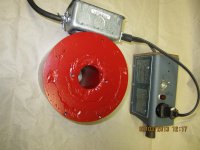
The power supply is operating at 167 volts DC from the power supply open circuit. When I plug in the magnet the voltage drops to 143 volts which with the (measured) 80 ohm magnet coil gives a calculated 1.8 amps (measured actual was 1.78) and power of 255 watts. The duty cycle of the magnet is a few minutes on at a time with equal or greater rest periods in between. In the few trials I have given it, the housing only gets a little warm after a few minutes. I don't figure I would ever leave it on long enough to overheat the magnet.
The attached photos show the magnet which is a cold rolled steel weldment. The OD is 6.25", the outer walls .375 thick, and the inner core is 3" OD with 3/4" walls. The top plate is 1/2" thick. I designed it so I could just stuff a full plastic spool of magwire into the hole without having to rewind the wire into a coil. I dug out the inner end of the wire and attached a lead and did the same for the outer end of the wire. Lined the inside of the magnet with the plastic stuff they use to line the slots in motor field windings. Stuffed the spool (trimmed off the excess plastic) sprayed in some insulating varnish to keep the outer loops of the coil from moving around too much and sealed it up with a 1/16" piece of stainless steel.
Some historical points and responses to jneutron's and metalsculptor's points:
Looks like I started some spirited conversation. I appreciate everyone's input. I have recalled a few more facts, check a couple things, and am including a couple photos for perspective.
The power supply is operating at 167 volts DC from the power supply open circuit. When I plug in the magnet the voltage drops to 143 volts which with the (measured) 80 ohm magnet coil gives a calculated 1.8 amps (measured actual was 1.78) and power of 255 watts. The duty cycle of the magnet is a few minutes on at a time with equal or greater rest periods in between. In the few trials I have given it, the housing only gets a little warm after a few minutes. I don't figure I would ever leave it on long enough to overheat the magnet.
The attached photos show the magnet which is a cold rolled steel weldment. The OD is 6.25", the outer walls .375 thick, and the inner core is 3" OD with 3/4" walls. The top plate is 1/2" thick. I designed it so I could just stuff a full plastic spool of magwire into the hole without having to rewind the wire into a coil. I dug out the inner end of the wire and attached a lead and did the same for the outer end of the wire. Lined the inside of the magnet with the plastic stuff they use to line the slots in motor field windings. Stuffed the spool (trimmed off the excess plastic) sprayed in some insulating varnish to keep the outer loops of the coil from moving around too much and sealed it up with a 1/16" piece of stainless steel.
Some historical points and responses to jneutron's and metalsculptor's points:
- Yes the automotive alternator rectifier is not ideal - I used it because back in the 1970's when I built the power supply, I had 10 or so of them lying around that I got free (used to work at a Chevy dealer and guys replaced them there whether they were good or bad). I figured it might work and if the higher than design voltage let the smoke out so be it, there would be no more harm than popping the power supply fuse from the mains. Hasn't popped yet. If it does, I'll use a bridge that meets the voltage specs.
- The inductor was added to the power supply - which originally only had the capacitor in parallel with the output because in the device's original incarnation the smaller magnet would buzz a little. I talked to a kid who was an electrical engineering student and he said to wind a coil around a long steel rod and put it in series with the load and it would "filter" out some of the ripple and give smoother DC to the magnet. He said the longer and skinnier the rod the better. So I tried it and it seemed to help. I looked today and the inductor is in series coming right out of the rectifier, before the capacitor in parallel across the output. It is the black thing sticking out the end of the power supply box in the photo. I figure the inductor does not (at least resistance wise - I'm not sure how power dissipation with inductance works) dissipate more than a few watts as it uses about 18 ga wire which is only a few feet long, maybe three or four layers around the 3/8" rod so the voltage drop across it would be minimal.


Attachments
Interesting Mag base drill nice work The inductor as it is currently used will have little effect on the magnet other than to reduce the voltage slightly. What it will do is smooth out the filter capacitor charging current peaks slightly. These peaks may be 10A along with the 1.8A magnet current which might explain the heating.
Thanks for complement. Kind of amaze myself when I remember I built the basic structure when I was a teenager using a torch, welder, grinder, and hand held 3/8" drill. And a hammer of course. Reminds me of the saying cut with an ax, beat to fit, and paint to match.
Woke up this morning with a few questions:
Woke up this morning with a few questions:
- Is the length of my new inductor critical? Making it a couple inches shorter would package better in the power supply box.
- Regarding suggestion to just eliminate all filtration, doesn't the capacitor help protect the system (esp. the diodes) from the voltage spike when I shut it off and the magnetic field collapses?
In my opinion, the capacitor there is useless. As current can't disappear suddenly in an inductor, nor the magnetic field, the own inductor smooths its current. Moreover, in case of resonance between cap and inductors, "big ball of fire" can get there, as voltage goes only limited by the Q of such a tank.
I would use only the bridge, an anti-parallel (freeweeling diode), and no more than this.
Or the other way is to use a simple 556 as fixed frequency PWM generator, and a power MOSFET to manage current in the coil.
I would use only the bridge, an anti-parallel (freeweeling diode), and no more than this.
Or the other way is to use a simple 556 as fixed frequency PWM generator, and a power MOSFET to manage current in the coil.
In my opinion, the capacitor there is useless. As current can't disappear suddenly in an inductor, nor the magnetic field, the own inductor smooths its current. Moreover, in case of resonance between cap and inductors, "big ball of fire" can get there, as voltage goes only limited by the Q of such a tank.
I would use only the bridge, an anti-parallel (freeweeling diode), and no more than this.
Or the other way is to use a simple 556 as fixed frequency PWM generator, and a power MOSFET to manage current in the coil.
I believe the cap does assist a bit, so I'd leave it.
But I concur with your freewheeling diode, nice idea.
PWM? While nice and something I'd certainly do, it adds too much complexity to an already elegant setup.
I would recommend however, that the rig have a 3 prong power cord so that all metal surfaces which could become energized by a short to housing are safe. Ground bonding is important.
dw..very nice project.
jn
Yes, PWM is an interesting way of control. But as I re-read my own thread, I was also thinking in a phase angle controller using a TRIAC in the primary of the transformer, but it may result in a dangerous rig, and also, the DC imbalance caused by the TRIAC asymmetry can conduce to transformer saturation. In such a solution, the capacitor MUST disappear.
Thanks. I'll add a flyback diode next time I go inside the box. Re the three prong plug, yes the device is grounded. The power from the mains comes into the outlet box on the side of the magnet 3 wire. The ground screws to the ground terminal on the duplex15A plug in the box and is jumpered to the screws mounting the box to the magnet. The two wire plug you see on the power supply feeds the output of the power supply to the magnet coil. The input to the power supply has no ground because there is nothing to ground there as everything but the wiring and fully enclosed electronics are plastic. I do have to put in a plastic handled and bezeled toggle switch to be truly double insulated.
There are several ways to reduce inductive kickback pulses:
1) by means of a hard clamp, as the diode in antiparallel, also a zener slightly upper in zener voltage, and connected in antiparallel with the coil, a tranzorb diode, a MOV, or a transil diode.
2) a soft clamp, like a RCD snubber or a simpler RC snubber..
Option 2 is personally my favorite. As high as the voltage at the capacitor is, the smaller the time needed to demagnetize the coil. Also, in case of a fault, is the less catastrophic of all of them.
Thanks. I'll add a flyback diode next time I go inside the box. Re the three prong plug, yes the device is grounded. The power from the mains comes into the outlet box on the side of the magnet 3 wire. The ground screws to the ground terminal on the duplex15A plug in the box and is jumpered to the screws mounting the box to the magnet. The two wire plug you see on the power supply feeds the output of the power supply to the magnet coil. The input to the power supply has no ground because there is nothing to ground there as everything but the wiring and fully enclosed electronics are plastic. I do have to put in a plastic handled and bezeled toggle switch to be truly double insulated.
- Status
- This old topic is closed. If you want to reopen this topic, contact a moderator using the "Report Post" button.
- Home
- Amplifiers
- Power Supplies
- Inductor for magnet power supply