I need an 18-24v supply for a jfet phono stage. I've run it on two 9v batteries and it works well, but it uses them up quickly. So I want to build a linear PS for the amp. I have built a lot of electronics with PS but I'm not a designer and I'm having trouble wrapping my head around this problem. Amp is cased separate from any PS.
I tried a simply CRC/Pi style supply, using a 12.6-0-12.6v filament transformer I had lying around. Transformer is 2 diode full-wave rectified (giving me the 18v output I want) with center tap connected to the PS ground.
Rectifier output goes into a 470uF cap, then 10R resistor, then into three 2200uF caps in parallel to ground. This then goes to a DC jack (wall-wart style) that then feeds the amp. Thus far the PS is NOT cased at all (it's breadboarded for now). As a result, nothing is connected to the mains ground (well, it is through the neutral at the box, of course).
The amp PCB has a ground plane which connects to the turntable ground lug which is isolated from the chassis. The power inlet negative is connected to the chassis and provides the only chassis connection to ground (turntable inputs and ground are on the front of the amp, power inlet and outputs on the back).
Hum is pretty bad, though the sound quality of the amp is pretty good - better, I think, than the batteries.
What have I done wrong? Thanks for any input. I'm a willing student.
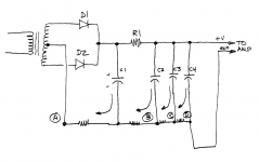
It's possible that your design is OK but its physical construction is not great. You want to connect the output ground (to the phono stage) after all of the capacitor connections -- see figure.
The physical wires that conect the center tap and the capacitor minus leads, are not perfect 0.0000 ohm superconductors. There are small (milliohm) resistances in the ground leads; I've drawn then as resistors between "ground A" and "ground B" and "ground C" et cetera. Capacitor ripple currents, drawn as curved arrows, flow through these resistors, so there will be ripple voltages produced. You don't want to pass these along to the phono stage, so you want to physically connect the "output ground" to point D, the very last point in the ground chain.
Maybe you could draw a similar "how it's actually constructed" diagram for the power supply you have now, and show how the center tap is connected to C1, C2, C3, C4, and the output ground.
Attachments
Thanks, Transistor. How great you drew this - sorry I didn't provide it (and yes, that's exactly what I've done).
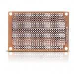
It's a bit hard to draw exactly as built as I'm using an old (previously used) Radio Shack prototyping board for the build which has parts going in odd directions because many of the copper pads beneath are shot. The ground is a bus in the middle of the board right next to another bus used for the + lead. But...not all cap negatives are connected directly to this bus. It's a bit of a mess, but functional and I've built like this before and not had problems.
Here's the board: http://www.radioshack.com/graphics/product_images/pRS1R-2265164reg.jpg
In answer to your question, though, the point at which the ground is pulled from the bus is just before the second cap, so what you say could be a factor. Easy enough to move that and try again.
I also realize the old board might cause some problems, but the hum was louder than I would have expected even for a crappy build. On the other hand, I've only built one other phono stage PS, and that was a bipolar supply for a Hagerman Bugle that was based largely on the PS schematic from Hagerman.
If I can get the hum down to a reasonable level, I'll re-build it better. Any value in throwing in an LM317 for regulation? I have a bunch of them around and considered it but wanted something simple to test the waters.
Thanks again!
PS - Oh, and for now I HAVEN'T twisted the transformer leads (duh, forgot to mention that) b/c everything is just floating and it untwists as soon as I let it go. I'll screw it all down to a board and twist the leads as soon as I get to work on it again.
Attachments
OK, I took a little time to work on this and pulled the amp ground from after the last cap as you suggested, twisted the transformer wires, then found the following:
1. The ground bus trace was broken and the last cap was not connected, so while I got output from my first build, it was with no help from it.
2. After fixing the ground bus, I got output of 18.5v or so using all 4 caps, with an AC component of 0.001v (according to my digital vom). AC had been more like 0.005v when I had only the 470uF first cap and the 2200uF second cap (other two caps were added later and I didn't measure AC component before moving the ground per your suggestion). I do have an old "boatanchor" scope that I'd hoped to use to measure the ripple but couldn't figure out how to get a good measurement from it.
3. Plug it into my phono amp, and I'm still getting hum just as bad as it was before.
4. Power "umbilical" is just two twisted wires (maybe 20-22ga), no shielding, and about 5 inches long, terminated with a DC jack.
5. Battery supply has a small amount of hum compared to the linear supply but it's very noticeable at full volume on my 2W SE tube amp (also DIY) which is otherwise VERY quiet into my 92dB +/- speakers.
Is there any problem having the amp case grounded at the power inlet? Should I be doing anything else with that?
I just tried connecting the PS floating ground (tied to the transformer secondary's center tap with no other connections) to the mains ground leg, but that had no effect at all on the hum. It's still breadboarded so no official star ground - no case for the testing period. Transformer primary just has connection to mains hot (load) and neutral.
Unless that JFET phono amp resembles a discrete op-amp, it just may not be very good at rejecting hum and noise from the power supply. Try the LM317 regulator.
One way to evaluate how quiet the power rail is just listen to it. Use a smallish battery-powered amp with a capacitively coupled input, like a headphone amp, or a small musical instrument practice amp. Or just the oscilloscope with an AC coupled input.
If the transformer is an annoyance, try an AC wall wart from the junk box or a thrift store.
Last edited:
No, I think you're right, it IS discreet jfet and single rail (not op-amp style) and isn't very good at rejecting PS noise. I was hoping brute force capacitance would solve the problem, but no luck so far. I tried one wall wart I had on hand and it was TERRIBLE but I'll probably try another. I will also next try an LM317 just for grins. I like the amp but could do without the hum.
No, I think you're right, it IS discreet jfet and single rail (not op-amp style) and isn't very good at rejecting PS noise. I was hoping brute force capacitance would solve the problem, but no luck so far. I tried one wall wart I had on hand and it was TERRIBLE but I'll probably try another. I will also next try an LM317 just for grins. I like the amp but could do without the hum.
Sometimes just throwing capacitance at the problem doesn't fix it.
A common method in valve amps is to use RC decoupling.
I have used this to good effect in my bipolar amps on the LTP and VAS stages.
Thanks, Nigelw.
I'm mostly a valve type guy, but I like the jfet approach and want it to tide me over until I can try Kevinkr's Muscovite tube pre. My next step for this will be to try to add an LM317 after the second cap (tuned to 17 or 18v), and add a 5R or so resistor between the 3rd and 4th caps and see what happens.
After some playing around, though, I'm finding the hum is pretty loud no matter what my configuration. Even my Yaqin MS12-B into my Marsh A200 amp gives a pretty loud hum at higher listening levels. Not sure it was that way always, but probably at least somewhat.
Commonalities are that the system is in a bay window of my living room, mostly sharing one outlet (though the TT is plugged into another outlet). There may be 3-5 inches height separating 3 levels of the audio rack (which is 2 shelves wide-6 shelves total). TT into the Yaqin with ground wire connected, then into Marsh amp results in audible hum - may not be as loud relative to the signal as the jfet preamp into the SE tube amp, but it's still pretty loud.
Carl
I rebuilt this PS switching to full bridge rectification (giving me 34v to start) into the first two caps of the original, and adding a LM317 set to pass 24v or so. Final cap was 22uF followed by 5R then into 3300uF final cap. Note that the jfet amp board has some PS decoupling on-board.
Hum is a bit reduced but still there. Then I went back to battery supply (two 9v in series), and lo and behold, the hum is still there at pretty close to the same level. So at this point the PS isn't adding any hum, but I still have hum!
The phono stage using the 9v has no AC, but the TT of course does. (Again, the amp is pretty quiet). Could the TT be passing AC on to the phono stage? Even without the TT turned on? The TT is Luxman PD-277, which has a power switch and a tonearm switch. Platter starts to turn when tonearm is moved to platter. Hum exists even when power to the TT is turned off, but it's louder when turned on, and even louder still as the tonearm moves toward the center and the platter motor.
Tomorrow I'll try disconnecting the TT leads, and if I can rig something up, try shorting RCA plugs on the inputs to see what that does.
I'm guessing this hum problem is bigger than just the PS...
Then I went back to battery supply (two 9v in series), and lo and behold, the hum is still there at pretty close to the same level. So at this point the PS isn't adding any hum, but I still have hum!
Tomorrow I'll try disconnecting the TT leads, and if I can rig something up, try shorting RCA plugs on the inputs to see what that does.
You do need to short the inputs to the jfet pre-amp to ground and see if you still have hum. Most likely the hum is being picked up on the input since you heard it while on batteries. You should hear no hum at all with the inputs grounded.
The input wiring going from your turn table to your jfet amp should be twisted, each signal input wire and a ground wire twisted together at 3 turns per inch or tighter.
Last edited:
Moving magnet and moving coil pickups both depend on coils.
Those coils by design are sensitive to receiving magnetic signals.
Good design of the magnetic circuit around and in the pickup would I think be part of what rejects external hum fields interfering with the wanted signal.
Those coils by design are sensitive to receiving magnetic signals.
Good design of the magnetic circuit around and in the pickup would I think be part of what rejects external hum fields interfering with the wanted signal.
Thanks, AGDR. I'll try to rig up something to test shorting the inputs soon. Is it OK just to jump a wire across the RCA connectors for each input? As for the wiring, someday I may replace it. What's there now is stock, and nothing special. But I'm just finishing up re-wiring another TT (Thorens TD-165) so it'll have to wait a little on this one.
AndrewT, can you elaborate? In particular, given the jfet circuit and board I'm using (you can see the circuit here: Boozhound Laboratories: JFET Phono Preamp Kit - similar to the Salas jfet phono here on DIYAuduo) what kind of circuit design could I use to help deal with the hum? An Aikido style approach where you inject inverse noise to counteract the noise? (That's beyond my skills to design.) Something else?
I agree with agdr that it seems likely it is being picked up on the input side, and clearly the AT440MLa is picking up AC hum from the motor as the hum increases as it moves toward the center of the LP (which is closer to the motor). I'll report back after shorting the inputs, and I need to look at the wiring of the TT and check grounding there.
Is it OK just to jump a wire across the RCA connectors for each input?
That link is very helpful to see what you are building. Yes, you can just jump across the inputs, ground to signal on each. If you are using RCA shorting plugs, just push them on. If you a are using a wire it would be a good idea to connect the ground end first since those jfet inputs will be pretty static sensitive.
A photo of your setup that shows the board-to-jack and jack-to-turntable wiring would be really helpful.
Last edited:
........... magnetic circuit around and in the pickup.............
Not the pre-amp. Look at the pickup...............the jfet circuit and board I'm using..............
Thanks for all the input.
OK, here's my update: Shorted or no inputs has NO buzz or hum. I also removed the ground wire and the hum was now a buzz. Bot seemed the same frequency, but with inputs it's a definite kinda muffled hum and with inputs but no ground it's a definite sharper buzz. A very different sound.
I'm in the midst of boiling maple sap for syrup but will try to grab a photo of the breadboarded PS. But no fair ribbing me about the rat's nest.
Edit:
Oh, and AndrewT, I figured you meant the cartridge, but thought maybe the circuit would help enlighten a solution. Short of trying things with grounding of the TT, I'm not sure what to do next. I won't be toying with the cartridge coils b/c I'd be sure to fork it up. That leaves "the magnetic circuit around...the pickup." that's the part I'm wondering about. I've not read anything about this and don't understand enough about coils, right-hand rules and magnetism (and all the fields dancing around the space near the pickup) to really work this out on my own.
Last edited:
Shorted or no inputs has NO buzz or hum.
OK, so that narrows it down to hum coming in through the input wires. Either powerline hum (fluorescent lights, etc.) picked up by the wiring itself, or as AndrewT says magnetic fields by a moving coil type of pickup.
If the wire, things now get interesting on grounding. Hum pickup is the same in both input wires, so if twisted it is up to the amp to cancel those common signals out ("common mode signals"). But your single-ended (single power supply, V+ and ground) amplifier design won't do that. It would take a differential input using +/- supplies. So with a single ended amplifier shielded mini coaxial cable is usually used instead, with the shield grounded, to keep the noise out. That only works for the distance from the RCA jack out to the tonearm though, where eventually the mini coax is too stiff and you have to go back to twisted pair, but then that is inside a metal (grounded) tonearm.
I just did an search and came up with a picture of the typical thing:
https://home.comcast.net/~tubes/Audio_Connections/Phono_Cart_UBal_Wiring.png
From here:
Turntable Forum • TD-160 wiring question
4th post down. The second link actually has two ways to do it. The top picture is especially slick if you have coax that has two conductors in the middle. You connect the shield to the chassis on the phono and chassis on the amp, but the amp ground goes to one internal wire and the signal line to the other.
And that maple syrup sounds wonderful! I'm a maple syrup fan, but only had the store bought variety. Mmmm.... fresh off the tree.
Last edited:
- Status
- This old topic is closed. If you want to reopen this topic, contact a moderator using the "Report Post" button.
- Home
- Amplifiers
- Power Supplies
- Help needed for 18v phono stage PS hum