Dear folks,
A few days ago we were in this other thread, trying to figure out why my +27V in the circuit below was probably oscillating very hard.
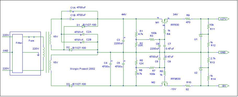
...supplying this:
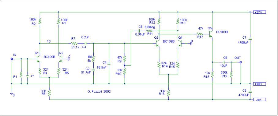
OK, so at some point I thought I had solved the TL431 issue, when it stopped failing, but I was left with a strong hum as soon as the 27V was reached (actually a tad later, when the MOSFET source voltage rose above 31-32V or so). Leaving the phono boards untouched (second picture), I played with endless capacitors values across R11 in the first picture, I played with the R9 resistor, and all I got was these possible cases: TL431 failing straight away at 27V output (mostly with no modifications), strong hum with voltage steady at 27V (with a 22uF electrolytic across R11), no hum but continuous *bumps* (27V - *bump* - 26,5V raising - 27V - *bump* - 26,5 V raising - all over again, with a 1uF multilayer cap across R11). I tried to bring Vsource of IRF630 lower than the schematics target, but problems showed up as early as at 31-32V, which makes no sense to me. On the other hand, raising R9 would just prevent the output to ever reach 27V, so it's not really viable, or so it seems.
I spent several days like that. I'm quite a bit frustrated and tired to mess with this, except if this last description may pop a brilliant solution from any of you, which I would still consider. (note that the -9V rail seems to work nicely)
If nothing good comes to your mind, I would ditch this kind of supply and look somewhere else, for example in building a nice battery power supply. Giorgio Pozzoli, designer of the inDiscreto, offered a scheme for a battery solution, but I don't really like it, because it relies on four cheap 9V batteries and you have, that way, almost no discharge margin in supplying good +27 and -9V.
I'd rather think of four SLA industrial 12V batteries, replicating what we have at the MOSFETs in the standard power supply illustrated above. We would have +36V on one end, and -12 on the other one. From that point on, I might choose a regulator solution to my likings; I may try again with TL431 (argh!), to see if a different source gives any benefit to their crazy behaviour, or stick with LM317/LM337's.
I might keep in use the rest of the supply, to power the recharge circuit. I mean everything, stopping at the IRF630 above and IRF9630 below. I would attach there a recharge circuit, if you give me some ideas on how to design that, then the batteries, and then the final +27/-9V regulation.
How does this sound to you guys?
Any ideas and thoughts, highly welcome.
Have a nice week,
Giacomo
A few days ago we were in this other thread, trying to figure out why my +27V in the circuit below was probably oscillating very hard.
...supplying this:
OK, so at some point I thought I had solved the TL431 issue, when it stopped failing, but I was left with a strong hum as soon as the 27V was reached (actually a tad later, when the MOSFET source voltage rose above 31-32V or so). Leaving the phono boards untouched (second picture), I played with endless capacitors values across R11 in the first picture, I played with the R9 resistor, and all I got was these possible cases: TL431 failing straight away at 27V output (mostly with no modifications), strong hum with voltage steady at 27V (with a 22uF electrolytic across R11), no hum but continuous *bumps* (27V - *bump* - 26,5V raising - 27V - *bump* - 26,5 V raising - all over again, with a 1uF multilayer cap across R11). I tried to bring Vsource of IRF630 lower than the schematics target, but problems showed up as early as at 31-32V, which makes no sense to me. On the other hand, raising R9 would just prevent the output to ever reach 27V, so it's not really viable, or so it seems.
I spent several days like that. I'm quite a bit frustrated and tired to mess with this, except if this last description may pop a brilliant solution from any of you, which I would still consider. (note that the -9V rail seems to work nicely)
If nothing good comes to your mind, I would ditch this kind of supply and look somewhere else, for example in building a nice battery power supply. Giorgio Pozzoli, designer of the inDiscreto, offered a scheme for a battery solution, but I don't really like it, because it relies on four cheap 9V batteries and you have, that way, almost no discharge margin in supplying good +27 and -9V.
I'd rather think of four SLA industrial 12V batteries, replicating what we have at the MOSFETs in the standard power supply illustrated above. We would have +36V on one end, and -12 on the other one. From that point on, I might choose a regulator solution to my likings; I may try again with TL431 (argh!), to see if a different source gives any benefit to their crazy behaviour, or stick with LM317/LM337's.
I might keep in use the rest of the supply, to power the recharge circuit. I mean everything, stopping at the IRF630 above and IRF9630 below. I would attach there a recharge circuit, if you give me some ideas on how to design that, then the batteries, and then the final +27/-9V regulation.
How does this sound to you guys?
Any ideas and thoughts, highly welcome.
Have a nice week,
Giacomo
Last edited:
Both rails has the TL431 shunt regs, but the current trough them is rather high, cind of close to the max limmit of 100mA. On the other hand i do not like one bit that so called rectifyer config on the upper rail, that is not verry good for audio circuits, i think it would be much better to get a power transformer with the proper voltages and quit that multiplyer alltogether, as long as you have regulated voltage then you have no voltage ripple, all that spider web of there is just asking for trouble, if the circuit powering up from this regulator does not need more than 50mA of current then just TL431 with maybe some compensation would do just fine, if the current is bigger then a small power transistor can be added to help.
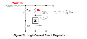
There's a nice idea in the datasheet of the TL431: connect an external transistor to conduct most of the current and let the LT431 control this transistor. See drawing. If you set Rz = 330 ohms then the TL431 will conduct (VBE / 330) = 2.1 milliamps, and the external transistor will conduct all the rest ... up to (Beta x 1mA) of additional current.
Attachments
The circuit is fubar. Overcomplicated.
Build the circuit with 48V CT transformer and bridge rectifier or a 24V transformer with symmetrical voltage doubler or whatever (symmetrical DC) or even 2 independent transformers (asymmetrical) and regulate with LM317 & LM337 to +27V and -9V.
Build the circuit with 48V CT transformer and bridge rectifier or a 24V transformer with symmetrical voltage doubler or whatever (symmetrical DC) or even 2 independent transformers (asymmetrical) and regulate with LM317 & LM337 to +27V and -9V.
Last edited:
- Status
- This old topic is closed. If you want to reopen this topic, contact a moderator using the "Report Post" button.