Hey Elvee, when you quote me, don't edit off the parts you don't like.
You edited out the most important line:

Thanks God you are not a Cop, or the following dialog might take place:
Scene: a dead guy with a shot through his head.
Officer one: "this guy has a shot in his forehead"
Officer Elvee: "NO ! NO! NO!! ABSOLUTELY wrong!!! this guy does not have a shot through his forehead, he has a 9mm shot through his forehead !!!!"
Thanks for being so funny, better reading your desperate posts than watching some comedy at Sony Channel.
You edited out the most important line:
How low can you fall?Quote:
Figure 6 . Current Limit
Thanks God you are not a Cop, or the following dialog might take place:
Scene: a dead guy with a shot through his head.
Officer one: "this guy has a shot in his forehead"
Officer Elvee: "NO ! NO! NO!! ABSOLUTELY wrong!!! this guy does not have a shot through his forehead, he has a 9mm shot through his forehead !!!!"
Thanks for being so funny, better reading your desperate posts than watching some comedy at Sony Channel.
What do you think happens to the graph, or §6, or the current, or anything when the die temp exceeds 160°C?Hey Elvee, when you quote me, don't edit off the parts you don't like.
You edited out the most important line:
How low can you fall?
..../snip crap/....
How do you call current falling in this case? Special name just made up for the occasion just to avoid the word "limit"?
@Elvee setting aside anything that might have been sayd untill now, i have a honest question and i need a honest answear:
-Do you honestly think the case temp can or should be allowed to reach 160deg? nevermind what the datasheet says, what do you say? do you allow it to go that far?
-Do you honestly think the case temp can or should be allowed to reach 160deg? nevermind what the datasheet says, what do you say? do you allow it to go that far?
Quote:
Originally Posted by JMFahey View Post
Hey Elvee, when you quote me, don't edit off the parts you don't like.
You edited out the most important line:
>>&&&&&&&&&&&&&&&&&&&&&&<< <--MISSING LINE
How low can you fall?
..../snip crap/....
What do you think happens to the graph, or §6, or the current, or anything when the die temp exceeds 160°C?
How do you call current falling in this case? Special name just made up for the occasion just to avoid the word "limit"?
You did it AGAIN !!!!
Second time you quote me editing out the basic phrase!!!
Are you out of your mind?
OK, that's an honest question, I will answer honestly: taking any device, particularly a plastic one beyond 150°C is generally not a good idea, even though the datasheet claims it can withstand "indefinite short" (beware of datasheet claims!).@Elvee setting aside anything that might have been sayd untill now, i have a honest question and i need a honest answear:
-Do you honestly think the case temp can or should be allowed to reach 160deg? nevermind what the datasheet says, what do you say? do you allow it to go that far?
But here the problem is somewhat different: as I said above, the dissipation in case of an overload will be practically sufficient to bring the die to 150°C, with the mounting base still at ~25°C. This means that most of the case will be at a reasonable temperature, with just the very heart of the chip at 160°C.
OK, it still creates thermal stress, etc, and that is not the kind of thing you want to abuse of, but in the case of the OP, the goal is to have a sort of automatic resettable fuse to protect the transformer.
Such an arrangement will work in this case: the initial overload current will be comprised between ~2.5A and 1A depending on the I/O differential, and most of the time that will be sufficient: the 317 will not have the opportunity to heat up to the thermal protection temperature, and the user of the supply will notice the voltage has dropped, and react accordingly.
If this situation lasts too long, the heatsink will heat up, and only then will the temperature reach 160° and reduce the current to a safe level.
That is not something that is going to be used systematically (hopefully).
A suitably sized PTC or polymer fuse could provide a similar kind of protection with the original 338, but the difficulty will be in choosing exactly the right one.
The advantage of the 317 and other "thermal" solutions is that they allow some overcurrent for some time, which can be useful to test amplifiers for example: a normal current limitation will clip each peak >1A on a cycle by cycle basis, even if the average current is much lower, but here there is a provision for more than twice the normal current provided things do not get too hot for too long.
It may not be the perfect solution, but I think it is a good trade-off that suits the needs of the OP. Additionally, it is simple to implement, predictable, and it doesn't in any way degrade the original performances of the regulator.
I answer to honest questions only, not provocations.You did it AGAIN !!!!
Second time you quote me editing out the basic phrase!!!
Are you out of your mind?
Quote:
Originally Posted by JMFahey View Post
You did it AGAIN !!!!
Second time you quote me editing out the basic phrase!!!
Are you out of your mind?
I answer to honest questions only, not provocations.
So my quoting exactly what the datasheet says is a provocation?
Tsk, tsk, I think we have a problem here.
@Elvee, i'm Happy to see that we are on the same page. Granted LM317 seams a better ideea that it's big brother, but anything will be used it will require a fuse rated so as it will blow at shorted ouptut cus in that case the reg will dissipate a great deal of power, so if let say the Vin is 24Vcc and the limmit at 2A that means over 48W of power will be dissipated by the regulator prior to overtemp prot comes in, if ther fuse is well rated than it will blow up as soone as the output will be shorted, and the fuse holder can be a pannel one so it can bea easy replaced, this way the unit is well protected but still as you say, it is not a verry good ideea to abuse it...
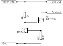
Another saolution could be this in the attachement, the current limit is the same with overload as with shorted output, there will be a few tens of volt drop on the series pass resistor depending on the load current but i think it can be worth it in many cases, the only real vdrop will be at current limmit when the voltage delivered to the load will drop in order to maintain the current, the limmit is verry precise and with a sturdy mosfet there should not be any problems, i luv IRF3205, especially it's Rds-on but the T220 case not so much... something in T247 case with as littl Rds as possible could be the answear in many cases.
PS: Agreed, LM317 only seams the best solutios here, but there can be sutiatuations in witch this CCG could be usefull.
Attachments
Another saolution could be this in the attachement, the current limit is the same with overload as with shorted output, there will be a few tens of volt drop on the series pass resistor depending on the load current but i think it can be worth it in many cases, the only real vdrop will be at current limmit when the voltage delivered to the load will drop in order to maintain the current, the limmit is verry precise and with a sturdy mosfet there should not be any problems, i luv IRF3205, especially it's Rds-on but the T220 case not so much... something in T247 case with as littl Rds as possible could be the answear in many cases.
That is indeed a possible solution, much better than trying to meddle with the regulator itself.
To make it completely transparent, it should be placed upstream of the regulator, and to make it safe, a 12V zener should be added between the gate and source of the MOS.
hi guys,
thanks for all the information. my plan for now is to replace the LM338 with a LM317 and add a fuse to the transformer's secondary in case of a short circuit. i would like to have a little wiggle room to overload the LM317, for when testing homemade amplifiers, without blowing the fuse while still providing protection in the case of a short circuit. would a 2.5A fuse be a good choice?
also, i'm interested in setting up a crowbar circuit but honestly i'm not really sure what situation it applies to. i dont think i've ever experienced an "overvoltage." what causes that?
...To make it completely transparent, it should be placed upstream of the regulator...
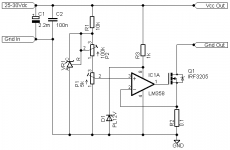
Good ideea, in fact here is an Iadj variant, this config permits precission current adjusting, or it can be set just above 2A in witch case it will not interfeer with voltage regulation untill after the treshold has been reached, an ahmmetter wired across the shunt can show the load current.
Attachments
A properly dimensionned fuse in the primary is all you need, see Andrew's answer.a fuse to the transformer's secondary in case of a short circuit. i would like to have a little wiggle room to overload the LM317, for when testing homemade amplifiers, without blowing the fuse while still providing protection in the case of a short circuit. would a 2.5A fuse be a good choice?
also, i'm interested in setting up a crowbar circuit but honestly i'm not really sure what situation it applies to. i dont think i've ever experienced an "overvoltage." what causes that?
A crowbar is a crude overvoltage protection that prevents extensive damage when everything else has failed. Complicated to implement on a variable supply, and not useful in your case, forget it.
That variant will mostly probably have stability issues: when you throw the gain and phase shift of an opamp into the game, compensation is almost always required. Better to keeps things simple and predictable.Good ideea, in fact here is an Iadj variant, this config permits precission current adjusting, or it can be set just above 2A in witch case it will not interfeer with voltage regulation untill after the treshold has been reached, an ahmmetter wired across the shunt can show the load current.
fit a close rated (CL) fuse in the primary circuit of the transformer.
Normal fuse for a transformer:
Fuse Rating = VA / Mains Voltage * 3
Close rated fuse for a transformer:
CL Fuse Rating = VA / Mains Voltage
VA / Mains Voltage = 0.454
is that right? i want a 0.5A fuse on the primary side? i guess it makes sense that there would be way less current on the primary..
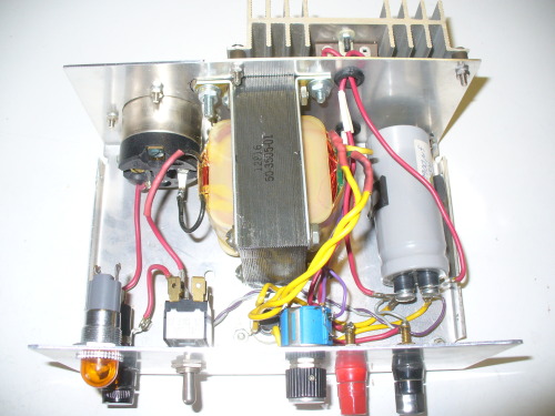
for some reason this power supply had a 10A fuse on the primary when i bought it.
Did Mr "for some reason" look like any of these?is that right? i want a 0.5A fuse on the primary side? i guess it makes sense that there would be way less current on the primary..
for some reason this power supply had a 10A fuse on the primary when i bought it.
An externally hosted image should be here but it was not working when we last tested it.
Did Mr "for some reason" look like any of these?
An externally hosted image should be here but it was not working when we last tested it.
that image is not loading. can you repost it?
Usually this will be marked:a 0.5A fuse
T500mA 250V
If this ruptures too often at start up, then fit a soft start. DON'T fit a bigger fuse.
Last edited:
I think you're cutting it too close. Usually a fuse should only carry 80% of it's rated current. The fuse is primarily there to prevent a fire. I'd use a 1A slow-blow. You may or may not need a soft-start. But, definitely get that 10A out of there.... i want a 0.5A fuse on the primary side? i guess it makes sense that there would be way less current on the primary..
thanks for all the advice. i went ahead and replaced the LM338 with a LM317K and the 18V/50VA transformer with a 24V transformer. i also replaced the fuse with a 500mA one. the new transformer doesnt have VA or current labelled but it is physically larger then the old transformer so i am assuming it is fine to use. now i have a safe to use adjustable 1.2-30V/1.5A supply.
i just need to have some small voltage and current meters to fit on the front panel.
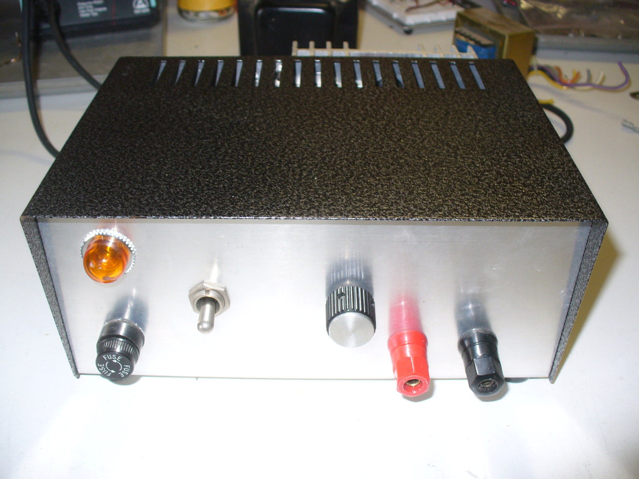
i just need to have some small voltage and current meters to fit on the front panel.
- Status
- This old topic is closed. If you want to reopen this topic, contact a moderator using the "Report Post" button.
- Home
- Amplifiers
- Power Supplies
- adding current limiting to a power supply