i picked up a homemade power supply from a swap meet recently and just opened it up to see how it works. it uses an LM338 as a voltage regulator at 22V and the transformer has a 24V/50VA secondary.
according to the datasheet, LM338 is rated for 5A and limits current at 12A. if my transformer is rated 50VA at 24V then doesn't that mean that i shouldn't draw more then 2.08A from it?
do i need to implement some additional current limiting circuit to ensure the LM338 does not draw more then 2A and damage the transformer? i was messing around with it today using it to power an amplifier and it was putting out 5A to 7A.
i was under the impression that crowbar protection prevents an over-voltage situation, caused by a failure in the power supply, which can damage the load.
crowbar wouldn't help in a situation where i am powering a device which draws more current then is safe for my transformer, right?
i guess i'll install a 2A fuse for the time being, but maybe i should just find a bigger transformer with the same current rating as the LM338.
crowbar wouldn't help in a situation where i am powering a device which draws more current then is safe for my transformer, right?
i guess i'll install a 2A fuse for the time being, but maybe i should just find a bigger transformer with the same current rating as the LM338.
"Crowbar" can apply to voltage or current. Think Ohm's law.
Perspective... If powering a device that draws too much current (let's use a loudspeaker as our example load), isn't it true that there is excessive voltage applied to the load?
There are active limiters, resettable circuit breakers, polyswitches, thermal switches, that you could seek out for your application. Then again...
You yourself can prevent a situation where you are powering a device which draws more current then is safe for your transformer, right?
Maximum DC current output will be about 1.2 A because a capacitor input filter has a current form factor of about 1.8 with a typical 50 VA transformer.
With a 1.2 A (DC) output current the transformer secondary current will then be around 2 A (RMS). Using a 2 A fuse in series with the secondary should protect the transformer.
With a 1.2 A (DC) output current the transformer secondary current will then be around 2 A (RMS). Using a 2 A fuse in series with the secondary should protect the transformer.
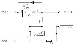
This scheme has many problems: it will ruin the regulation, and in case of dead short (Vout<0.6V), it will not limit and it will fry the transistor .Just like LM317, LM338 offers a simple and safe way for current limmiting on single supply, choose R3 by 0,65/Iout
Better to replace the LM338 with a LM317 or LM350.
Only when reaching the threshold the output will be affected, but then again any current limmiting acts about the same, it reduces the voltage to keep the current at a needed level, so no problem here.This scheme has many problems: it will ruin the regulation...
Easy fix:...and in case of dead short (Vout<0.6V), it will fry the transistor...
Attachments
Only when reaching the threshold the output will be affected, but then again any current limmiting acts about the same, it reduces the voltage to keep the current at a needed level, so no problem here.
Easy fix:
hmm, so the current limiting shouldn't impact voltage regulation until i reach the current threshold? what happens at that point? the voltage drops slightly?
would a 2n3904 be a suitable substitute for the BC546A? do i need a heatsink on the BJT?
R4 = 0.65 / Iout. so if i want to limit at 2A then R4 = 0.325ohms? what power rating will i need on this resistor?
a) It will impact the regulation at any current levelhmm, so the current limiting shouldn't impact voltage regulation until i reach the current threshold? what happens at that point? the voltage drops slightly?
b) On a dead short, the current limit will be double the normal
A LM317 is cheap compatible with the LM338, does the job perfectly and won't lead you into troubles like oscillations
Current limiting ( aka constant current generator ) work like this: When some chosen threshold is reached the voltage is dropped so the current chosen can be maintained, you cannot have the same voltage and same current for any load level, let say you have a resistive load of 10 Ohm and an output voltage of 20V, that makes a load current of V/R =>20/10 =>2A, now let say we drop the load to 5 Ohm but we want the same voltage on that new load and the same 2A, well that is impossible cus as we have pointed out already I=V/R =>20/5 =>4A; what then? well if we need the same current we drop the voltage, and V=I*R =>2*5 =>10V. That is how current limmiting works, it reduces the voltage to maintain the current in needed limits.
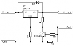
Any NPN small signal transistor will do as long as the Vce of it it's larger than any espected Vin on the regulator ( that is just to be sure ), it does not need a heatsink cus it will work only when the limit is reached and it will dissipate a small enough power, the resistor indeed would have to be 330m Ohm for 2A limmit and it's power rating P=V*I =>0,65*2 =>1,3W, make it 2 or 3W.
Any NPN small signal transistor will do as long as the Vce of it it's larger than any espected Vin on the regulator ( that is just to be sure ), it does not need a heatsink cus it will work only when the limit is reached and it will dissipate a small enough power, the resistor indeed would have to be 330m Ohm for 2A limmit and it's power rating P=V*I =>0,65*2 =>1,3W, make it 2 or 3W.
No, it will not, maybe you should study more of this config... as long as the voltage across the shunt resistor is less than 0,5-0,6V the transistor will not enter conduction, and let say that the load is 1A, on a 330m Ohm resistor will be 330mV, that is too small a voltage to biass the BE of it, so no, only near the threshold when Vbe will be big enough the regulation will be affected.a) It will impact the regulation at any current level...
The regulator already has internal shortcircuit protection and so it will not be affected, and the NPN will be protected by the base resistor, so nothing bad can happen at a shortcircuit, and anyway nowone will short a PSU just for the fun of it, that can only happen accidentaly so in short periods/time and as i have pointed out it cannot affect the regulator.a) b) On a dead short, the current limit will be double the normal...
There are no oscilations here, both the regulators are about the same, only this one can handle more current, on the other hand LM317 would only giv about 1,5A, and here it is needed 2A, i think it is the best way to go...A LM317 is cheap compatible with the LM338, does the job perfectly and won't lead you into troubles like oscillations
Last edited:
There has been replies while I typed, but I'll add this anyway.
I don't remember seeing this circuit before, but it seems easy enough. It's sort of the series pass transistor concept in reverse. When the R4 IR drop reaches a level to turn on the transistor, current is shunted away from the adjust pin. That reduces the regulator output voltage, and also the current.
It will impact the regulation at the load; there will always be a drop across R4 that is unseen by the regulator.
A 2N3904 can substitute. No heat sink needed.
Yes there will be some voltage drop on the shunt but small enough though, anyway if mV precission and current limiting is needed then this tipe of regulator will not do, then more complex regulators should be used, but i am sure that is not the case here, a couple of hundreds mV of voltage drop will not be souch an issue.
You should probably study more carefully this configuration: the 0.33 ohm is in series with the output, and it will add an uncertainty between 0 and 0.6V on the output voltage. This makes it useless as a lab supply. If you set it 3.3V to supply logic circuits, it could drop to 2.7V under load.No, it will not, maybe you should study more of this config... as long as the voltage across the shunt resistor is less than 0,5-0,6V the transistor will not enter conduction, and let say that the load is 1A, on a 330m Ohm resistor will be 330mV, that is too small a voltage to biass the BE of it, so no, only near the threshold when Vbe will be big enough the regulation will be affected..
The purpose is to protect the transformer and rectifier against overloads.The regulator already has internal shortcircuit protection and so it will not be affected, and the NPN will be protected by the base resistor, so nothing bad can happen at a shortcircuit, and anyway nowone will short a PSU just for the fun of it, that can only happen accidentaly so in short periods/time and as i have pointed out it cannot affect the regulator.
If the limitation is incapable to do that in case of a short, it defeats its usefulness.
When you add loop gain (transistor) to a regulator, you eat up the stability marginsThere are no oscilations here,
@Elvee you seem to enjoy contradicting me just for the fun of it...
ANY active current limiting would imply a shunt resistor and so a voltage drop on it, but it is small enough so you are not worryed, and for the life of me i cannot understand what is souch a BIG issue few tens of volts drop? the author did not mention the exact purpose of the supply, but as i sayd mV preccision and preccision current limmiting is not likely to happen with thys tipe of regulator.
On the other hand, yes the config really has overload protection witch is different from shorted outputs, you cannot hope to have a linear regulator imune to indefinitly shorts on the output without serious upgrades, and so you make sure that any shorts will be... whel short in time, and any 50/60Hz power transformer can cope with shorted outputs for a max of a few seconds, but not even that would not happen, you guess why.
This woulb be much more precise on voltage regulation but the current limmit is not so, you rely on the regulator's limmit of about 1,5A and the rest of the current is given by the pass transistor
Attachments
Last edited:
Just looking at the datasheet
http://docs-europe.electrocomponents.com/webdocs/0028/0900766b80028b1f.pdf
On page 8 you can see how the LM338 is used in current limiting mode. AFAICR you need to keep the adj pin at <1.25V. So if you want to limit the current to 1.5A you are looking at using R(limit) = 1.25/1.5 = 0R82.
Unfortunately the second regulator will swallow another 3.5V of your available ouput.
Last edited:
- Status
- This old topic is closed. If you want to reopen this topic, contact a moderator using the "Report Post" button.
- Home
- Amplifiers
- Power Supplies
- adding current limiting to a power supply