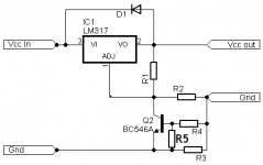
Voltage dropping under load and doubled current limit at shorted output can be solved like the attached schematic. Select current limiter divider ratio so that current limit happens with about 1.4 V over the resistor. (NPN Vcesat + LM317 reference voltage)
However, the current limit will still not be very temperature stable and it will also be very "soft", starting to reduce the output voltage long before the full current limit is reached.
With the original circuit output voltage drops about 0.6 V from no load to full load. That's quite a lot if you want to power logic circuits that may want 5 V +- 5 % or even worse 3.3 V +- 5 %.
If needed, a miller capacitor for the NPN transistor might help stability.
Also note that the 50 VA / 24 V transformer is still not up to the job of supplying 2 A DC!
Attachments
That's the point ")
You don't even need R5 , just use R3= 0.33 ohms and you limit at 2A.
Need another current value?
It'll be 0.65V/R3 .
Yes, limiting will be somewhat soft and also somewhat temperature dependent.
Anyway the idea is not turning this into a precision constant current supply (there are better methods for that, of course) but adding short circuit protection.
In fact, adding just an extra resistor, you can turn this into a "foldback" current protection and reduce short circuit current to somewhat over 1 A , halving the regulator dissipation under such stress.
No nuclear science here, these linear PSU regulators have been around for a *long* time.
You should at least read my previous posts. Megajocke just said the same (and he even provided a solution to the problems, but even with these fixes, I still don't think this scheme is worth implementing).You have no idea.
"Precision" refers to the built-in precision of the regulator.
Just check the datasheet.
Does it state 0.1% or whatever? Well, that's what you'll get.
50% error?
Not even an unregulated supply will be that bad
Current can reach 4A ?
Who says so?
Didn't I tell you the OP can current limit it to *any* value he wants?
When the limitation becomes active, the transistor becomes a voltage amplifier. Its input will be connected to the regulator's output via the output bypass capacitor. Its transconductance is set by the emitter current, which itself is set by the 120ohm divider resistor and the 1.2V reference. The transconductance is therefore 0.01/0.026=0.384S. The resulting gain is ~120*0.38=45.6.Loop stability in the current limit?
Don't worry about that , all these regulators are *designed* to be able to be current limited.
No designer worth his salt will release an unstable design.
Regulators are designed to be stable on their own down to a gain of 1, and have some stability margins.
But when you add the 45.6x in the loop, it has to operate at a gain much lower than unity: more than 33dB in this case. This will eat up all the margins Bob Pease and others have painstakingly built into their design.
The end result could be stable -or not-
I relish that kind of remark: I come from the country of surrealismThink a little and you will too
You don't even need R5 , just use R3= 0.33 ohms and you limit at 2A.
You do need it if you don't want the current limit value to double when the output voltage is reduced below 0.6 V, which is the very problem it was introduced to fix! Regardless of how hard that transistor conducts it can't reduce the voltage over the sense resistor to below the LM338 reference voltage (1.25 V) when the output is shorted.
Last edited:
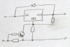
People this is overkill by so far, nevermind @Elvee witch seam that nothing can please him, but think about this: This config is presented on the datasheet of the reg, no voltage divider in the NPN's base, no miller cap, just the shunt, the transistor and the reg's feedback resistors, so it the producers recommend something don't you think that is after they would have tested it? and as theyr test went ok why shouldn't it work for us? for the topik's author... i repeat, this is overkill, we aren't developing rocket science here, just some damned simple linear regulator... quit beying so picky, it is a mear 50VA transformer for God's sake, and you are confusing the hell out of @dietnews in stead of helping him.
You don't like me , do you? Problem is, there is nothing personal: components do not not care about likes/dislikes of humans, or their arguments: they just obey the law of physics, and they tend to be rather inflexiblePeople this is overkill by so far, nevermind @Elvee witch
In the applications, they recommend lots of things, they also say that a 317 can regulate voltages much higher than its abs max ratings. I have seen the result of gullible people accepting that kind of assertion on their face value: hundreds of blown regulators.This config is presented on the datasheet of the reg, no voltage divider in the NPN's base, no miller cap, just the shunt, the transistor and the reg's feedback resistors, so it the producers recommend something don't you think that is after they would have tested it?
People in the application department are in the business of selling as many devices as possible, and sometimes the designer himself cringes at what is proposed, but there is little he can do (sometimes he does: I think Pease and others sometimes distanced themselves from what was advertised).
Anyway, I said it could work, -or not- and I don't change my opinion.
No, no rocket science, but even simple things can be messed up: some people manage to under- or overcook soft eggs. Everything should be done right, especially simple ones: you then have no excuses for doing it wrong if it is that simple.for the topik's author... i repeat, this is overkill, we aren't developing rocket science here, just some damned simple linear regulator...
I am not sure the OP has the same opinion: he came here in the first place because he was concerned about the health of his <measly 50VA> transformer. I think it is just decent to give him reliable information. I normally wouldn't have intervened in this thread, I just did because he was given poor advice.quit beying so picky, it is a mear 50VA transformer for God's sake, and you are confusing the hell out of @dietnews in stead of helping him.
I think he now has all he needs to decide for himself what is best for him.
i'm just trying to get a sense of what my options are for current limiting. this is a $10 power supply without any particularly specific purpose. i wanted to try my hand at building some power supplies and i came across this one at a swap meet. i want to build an adjustable 1-30V/5A supply and thought that messing around with this supply would provide some good experience before i build something from scratch. i already have a 1-30v/1.5A hp supply which i use for bench tests.
elvee, is your position that i shouldn't be adding any additional current limiting circuits and instead use a smaller voltage regulator—such as lm317—and leave the current limiting to the regulator?
elvee, is your position that i shouldn't be adding any additional current limiting circuits and instead use a smaller voltage regulator—such as lm317—and leave the current limiting to the regulator?
I am not sure the OP has the same opinion: he came here in the first place because he was concerned about the health of his <measly 50VA> transformer. I think it is just decent to give him reliable information. I normally wouldn't have intervened in this thread, I just did because he was given poor advice.
I think he now has all he needs to decide for himself what is best for him.
That's what I understood from the beginningi'm just trying to get a sense of what my options are for current limiting. this is a $10 power supply without any particularly specific purpose. i wanted to try my hand at building some power supplies and i came across this one at a swap meet. i want to build an adjustable 1-30V/5A supply and thought that messing around with this supply would provide some good experience before i build something from scratch. i already have a 1-30v/1.5A hp supply which i use for bench tests.
Yes: from a pure performance perspective, a LM317 is a less than ideal current regulator (it is the scaled down version of the 338 or the opposite if you prefer), but it has all the attributes you need: when cold, it will initially limit at 2~3A, but as soon as it heats up, the limit will drop: to 1.5A on a very large heatsink, somewhat less on a real one.elvee, is your position that i shouldn't be adding any additional current limiting circuits and instead use a smaller voltage regulator—such as lm317—and leave the current limiting to the regulator?
That is just the behavior you want to protect your transformer: transformers have a good deal of thermal inertia, and can tolerate abuse for some time.
Long term overload will fry them, and you need something that will reduce the current if the surge lasts too long. Also remember what megajocke said: the rms current seen by the transformer will be ~2x the DC output current.
A LM317 on a not too large heatsink, not too far from the transformer will do exactly that.
Additionally, the circuit will remain unconditionally stable, and the regulation will not be degraded in any way.
That doesn't dispense you from using a proper primary fuse: you don't want to set fire to your house in case something goes seriously wrong.
The 317 fix is simple, inexpensive and effective.
On the other hand if you want to make a full-blown lab supply, you should use specific circuits: LM317/338 based regulators are designed as system power supplies and work poorly when coerced into that kind of job.
Many schemes can be found on the web (and here), that will give you 0 to max variation for current and voltage without excessive drop out or similar inconvenients, but I don't think that is what you are looking for.
If you want to keep the 338, megajocke's solution is the way to go, but some shady areas remain, as he himself said.
Last edited:
Theoretically, the transformer secondary should be about 1.6x the DC output. Here's a concise reference for power supply types.
Where do you get of with this ridicoulus so called advices? and better yet, what gives you the right to consider yoursel better then those that wrote a component's pdf? cus that is just what you have implyed when you last quoted me....when cold, it will initially limit at 3A, but as soon as it heats up, the limit will drop: to 1.5A..
Now LM317 limmits the current accordingly with the Vin-Vout differential, don't believe me, just take a look at the attachement... oh i forgot, you are way better than the ones that produced the component, ofcourse you know better then them... Anyway, at a shortcuircuit on the output things will be just about the same for the transformer, the regulator will be protected but it will put great stress on the power transformer just like the othe regulator, nothing new here. Now don't missunderstand me, i like LM317, it is simple and cheap, most of the time an easy fix for small jobs, but let's not make it more than it is.
Attachments
That is something else: it is the SOAR protection. It reacts instantly and depends little on temperature.Now LM317 limmits the current accordingly with the Vin-Vout differential, don't believe me, just take a look at the attachement... .
I am talking about the thermal limitation: when the regulator dissipates ~25W or more, the heat flow through the 4°C/W of the regulator itself plus the interface to the heatsink will already be sufficient to bring the die to the temperature of thermal safety, even on a cold, large heatsink. The current will be reduced to stay below the limit, and when the heatsink begins to heat up, the current will be reduced further.
That is the reason why I said the heatsink must not be too large, so that it heats up faster than the transformer.
You say it as if it were a different thing.That is something else: it is the SOAR protection.
SOAR protection is a type of current limiting.
Which is exactly shown in the graph.
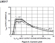
Just in case the type is too small to read, in the bottom of the graph it says:
Figure 6 . Current Limit
The maximum current obtainable from LM317 is at a range of about 4 to ~11V Vin-Vout difference, the graphic shows that in that range at 25deg junction temp the max current is just over 2A ( maybe 2,2 or somthing like that ), at 150deg that current drops to just below 2A ( maybe 1,8-1,9A ), that is all you need to know cus i doubt verry much you will allow the junction temp to rise above 150 no matter what.
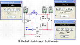
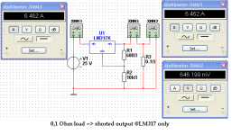
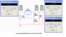
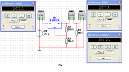
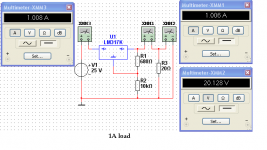
Sorry for the double posting but i cannot edit the last one. I was playing around with Multisim and tested a bit LM317, the immages speak for them selves:
Attachments

What are you trying to say?
That the simulation shows 6.5 A with shorted output contradicts your previous graph from the datasheet which says the current limit is 1 A at a 25 V input-output differential.
If some simulation model of unknown origin contradicts the manufacturer's datasheet it's probably the datasheet that should be trusted!
The LM317 and similar regulators include three different types of protection: plain current limiting at low I/O voltages (up to ~12V, flat part of the graph), SOAR for I/O >12V and overtemperature protection, when the die T° exceeds ~160°C.You say it as if it were a different thing.
SOAR protection is a type of current limiting.
Which is exactly shown in the graph.
Just in case the type is too small to read, in the bottom of the graph it says:
All of these mechanisms result in current reduction, because that is the only parameter the chip can control, but they are completely distinct.
They all operate concurrently: the first limit that is exceeded dictates the output current
Your multisim model is obviously wrong: it contradicts the datasheet and the actual behavior of a 317.Sorry for the double posting but i cannot edit the last one. I was playing around with Multisim and tested a bit LM317, the immages speak for them selves:
Transistor helps, that is true no matter what some people say.What are you trying to say?..
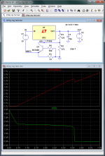
The expected behaviour for a 1.25 V three terminal regulator with a high internal current limit is shown in the attached graphs.
The X-axis is the output voltage and the green graph shows the output current as a function of the output voltage. As can be seen, the current limit doubles at low output voltage.
The reason can be seen in the red graph which shows Q1 Vce. The transistor saturates below 0.6 V output voltage. When the output is shorted (0 V) the full 1.25 V reference voltage will fall over the sense resistor, giving an ouput current of twice the nominal value.
Attachments
- Status
- This old topic is closed. If you want to reopen this topic, contact a moderator using the "Report Post" button.
- Home
- Amplifiers
- Power Supplies
- adding current limiting to a power supply