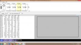
Same with .026R 1500uf throughout just for direct comparison to last pic with 1R transformer
That looks right.
Agreed. I just wanted to show how the standard schematic simulates vs the 100r ESR. The one that looks right is the standard values.
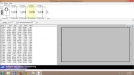
I know PSUD is giving false values but at what point do the values stop simulating reality and start being totally false? If I sim with low ESR cap at .026R and then use the same cap with 1R or even .05R the numbers look like less noise.
So it seems like its not just with large ESR that it gives false results. Ill show you. Here is a schematic with .02 ESR, .08ESR and 100ESR caps. Each of first twoare rather normal and last is extreme but common to all is higher ESR = lower noise.
Each has better noise than the previous. Does PSUD work at all considering this?
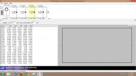
Attachments
Last edited:
Agreed. I just wanted to show how the standard schematic simulates vs the 100r ESR. The one that looks right is the standard values.
I know PSUD is giving false values but at what point do the values stop simulating reality and start being totally false? If I sim with low ESR cap at .026R and then use the same cap with 1R or even .05R the numbers look like less noise.
So it seems like its not just with large ESR that it gives false results. Ill show you. Here is a schematic with .02 ESR, .08ESR and 100ESR caps. Each of first twoare rather normal and last is extreme but common to all is higher ESR = lower noise.
Each has better noise than the previous. Does PSUD work at all considering this?
Could it be the resistance of the capacitors you have in the sim? I usually just plug in 1 Ohm there....
Cheers,
Bob
I found an article on Planet Analog ( I think it was linked to by someone in one of Gootee's cap decoupling/paralelling threads). Here is the article
Planet Analog - Articles - Know the sometimes-surprising interactions in modelling a capacitor-bypass network
It shows how in the many megahertz range a higher ESR allows a overall lower impedance to higher frequencies. Do you think PSUD is simulating this behavior?
Their summary is pasted below. See point 5
Summary
Here's a summary of bypass considerations raised by this article:
1. Bypass close to IC pin and ground (minimize Rseries for deep notches, optimize it for smoother overall impedance)
2. Use multiple values in broadband applications (or in the presence of broadband noise), spacing the resonant frequencies out over the band you need to cover
3. More capacitors won't hurt the power supply! They just add area, cost and design time.
4. To be sure, simulate (any simulator will do, even a free one). Quantify parasitics and model correctly, applying common sense to the component parasitic values
5. Loss can be good! Higher-performance capacitors may not be best in your circuit.
6. Resonance (impedance nulls) can be useful, be sure to predict and employ
7. Anti-resonance (impedance peaks) can get you into trouble, so predict and avoid!
Last edited:
Another article talking about the increase of ESR allowing a smoother supply
Yet more on decoupling, Part 2: Power supply excitation and ringing | EE Times
They are talking about caps directly after an LDR but nevertheless we see that just large capcitance isnt the cure all. Some ESR is good along with bypassing the large cap.
Here is their summary:
Takeaways from this part:
Whatever the LDO datasheet says, high-ESR output capacitors give better control of high-frequency supply resonances
The smaller you make the main ceramic decoupling capacitor, the faster and larger will be the ringing that occurs on a load current step - this is a small-signal effect and occurs for any current change, not just large ones.
If you are designing audio circuits that don't have impeccable power supply rejection, the LDO regulator impedance bump could cause coloration as it usually occurs within the audio band. Huge output capacitors don't cure it, in fact they could make it worse. Use that noise bypass connection.
Zorbel circuit or tuned resonator in the rf range with high esr.Another article talking about the increase of ESR allowing a smoother supply
Yet more on decoupling, Part 2: Power supply excitation and ringing | EE Times
They are talking about caps directly after an LDR but nevertheless we see that just large capcitance isnt the cure all. Some ESR is good along with bypassing the large cap.
Here is their summary:
Takeaways from this part:
Whatever the LDO datasheet says, high-ESR output capacitors give better control of high-frequency supply resonances
The smaller you make the main ceramic decoupling capacitor, the faster and larger will be the ringing that occurs on a load current step - this is a small-signal effect and occurs for any current change, not just large ones.
If you are designing audio circuits that don't have impeccable power supply rejection, the LDO regulator impedance bump could cause coloration as it usually occurs within the audio band. Huge output capacitors don't cure it, in fact they could make it worse. Use that noise bypass connection.

- Status
- This old topic is closed. If you want to reopen this topic, contact a moderator using the "Report Post" button.
- Home
- Amplifiers
- Power Supplies
- PSUD high ESR question